11 Common Injection Molding Defects and Proven Remedies for Better Production Outcomes
Injection molding is a precise and complex manufacturing process, yet it is not immune to defects that can compromise product quality and production efficiency. Understanding these defects and their remedies is crucial for achieving optimal outcomes in your molding projects.
1. Sink Marks
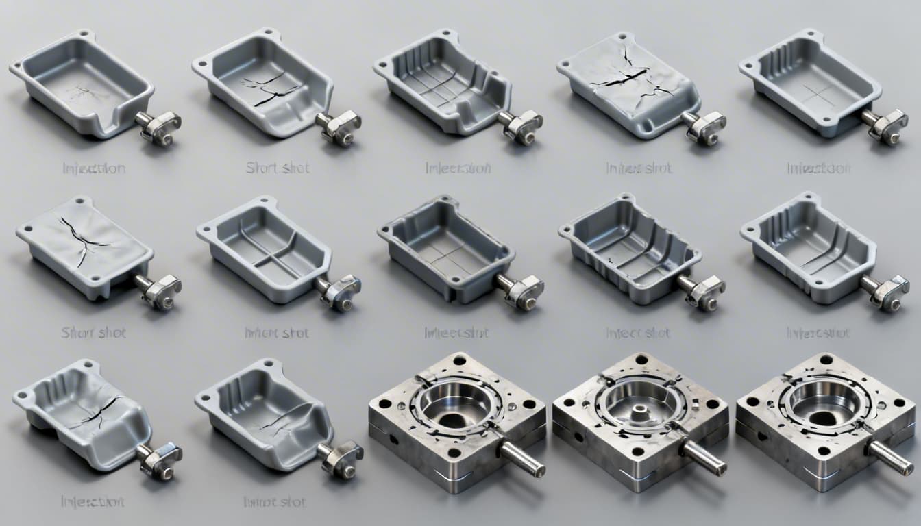
Sink marks are depressions on the surface of molded parts, typically occurring in thicker sections where the material shrinks unevenly.
Causes
The primary cause of sink marks is insufficient packing pressure or inadequate cooling time, leading to differential shrinkage.
Solutions
- Increase packing pressure and time to ensure complete filling and compaction of the material.
- Optimize cooling time to allow uniform solidification. Aim for a mold temperature of 20-80°C depending on the material used.
- Design parts with uniform wall thickness, ideally between 1-3mm, to minimize shrinkage variations.
2. Warping
Warping is a distortion that causes parts to bend or twist, usually due to differential cooling rates within the mold.
Causes
Uneven temperature distribution and material flow can lead to warping.
Solutions
- Ensure uniform mold temperature control to promote even cooling. Maintain mold temperatures within 30-70°C for materials like ABS and PP.
- Adjust injection speed and pressure to ensure consistent material flow.
- Incorporate design features like ribs and gussets to enhance part stability.
3. Flash
Flash occurs when excess material escapes the mold cavity, creating thin protrusions along the parting line or ejector pins.
Causes
Flash is often caused by excessive injection pressure or poorly fitting mold components.
Solutions
- Reduce injection pressure to minimize material overflow.
- Ensure precise mold alignment and maintenance to prevent gaps.
- Use appropriate clamping force to secure the mold halves, typically 2-5 tons per square inch of projected area.
4. Short Shots
Short shots occur when the mold cavity is not completely filled, resulting in incomplete parts.
Causes
Insufficient material flow or low injection speed can lead to short shots.
Solutions
- Increase injection speed and pressure to improve material flow into the cavity.
- Ensure proper venting to allow air to escape from the mold cavity.
- Use higher melt temperatures, within material-specific limits, to enhance flowability. For example, 220-260°C for ABS.
5. Weld Lines
Weld lines are visible lines on the surface of molded parts where two flow fronts meet.
Causes
These occur due to inadequate material temperature or improper flow paths.
Solutions
- Increase melt temperature and injection speed to improve material fusion.
- Modify gate locations to ensure better flow paths and minimize flow front convergence.
- Consider using materials with better flow characteristics, such as PA66 or POM.
6. Burn Marks
Burn marks are discolorations or charred areas on the part surface, often caused by trapped gases.
Causes
Excessive injection speed or poor venting can lead to burn marks.
Solutions
- Reduce injection speed to minimize heat generation and gas compression.
- Enhance mold venting to allow gases to escape effectively.
- Check for obstructions in the venting system and clean regularly.
7. Voids
Voids are air pockets trapped within the molded part, often leading to structural weakness.
Causes
Poor material packing or excessive shrinkage can result in voids.
Solutions
- Increase packing pressure and time to ensure complete material filling.
- Optimize cooling rates to allow uniform solidification and minimize shrinkage.
- Consider using lower shrinkage materials like PC or TPE.
8. Jetting
Jetting is a defect characterized by a wavy surface pattern due to inconsistent flow of the material.
Causes
Jetting occurs when the initial material flow is too fast, causing turbulence.
Solutions
- Reduce injection speed to allow a more controlled and laminar flow.
- Optimize gate design to promote smooth flow patterns.
- Increase melt temperature slightly to improve material fluidity.
9. Delamination
Delamination is the separation of layers within a molded part, often due to contamination or incompatible materials.
Causes
Contaminants or incompatible material blends can cause delamination.
Solutions
- Ensure material purity by using virgin resins and maintaining clean processing conditions.
- Avoid mixing incompatible materials, and check material compatibility charts.
- Control processing temperatures to prevent overheating and degradation.
10. Surface Defects
Surface defects include blemishes, roughness, or gloss variations that affect the part's appearance.
Causes
Inconsistent mold surface finish or improper processing parameters can lead to surface defects.
Solutions
- Ensure uniform mold surface finish with appropriate polishing techniques.
- Maintain consistent processing parameters, including melt and mold temperatures.
- Use surface treatment techniques like texturing to enhance appearance.
11. Ejector Marks
Ejector marks are indentations or marks left on the part surface by the ejector pins during ejection.
Causes
Improper ejection force or misaligned ejector pins can cause these marks.
Solutions
- Optimize ejection force to minimize surface damage while ensuring part release.
- Align and maintain ejector pins to prevent uneven pressure distribution.
- Consider using ejector sleeves or softer pin materials to reduce marking.
| Material | Melt Temperature (°C) | Mold Temperature (°C) | Shrinkage (%) |
|---|---|---|---|
| ABS | 220-260 | 50-70 | 0.4-0.8 |
| PP | 180-240 | 20-60 | 1.0-2.5 |
| PC | 270-310 | 80-100 | 0.5-0.7 |
Checklist for Optimizing Injection Molding Processes
- Ensure proper mold design with uniform wall thickness and adequate venting.
- Maintain precise control over processing parameters: injection speed, pressure, and temperatures.
- Regularly inspect and maintain molds and equipment to prevent wear and misalignment.
- Use quality materials and avoid contamination to ensure consistent part quality.
- Conduct trial runs and adjust settings based on real-time feedback and results.
Practical Tip: Always conduct a thorough analysis of defects using techniques like mold flow simulation to identify root causes and implement effective solutions.
For professional assistance with your injection molding projects, get a free quote from Panda Molding.
Conclusion
Injection molding defects can significantly impact product quality and production efficiency. By understanding the common defects and implementing the proven remedies outlined above, you can enhance your molding processes and achieve better production outcomes. Remember, consistent monitoring and optimization of your injection molding parameters are key to minimizing defects and maximizing productivity.