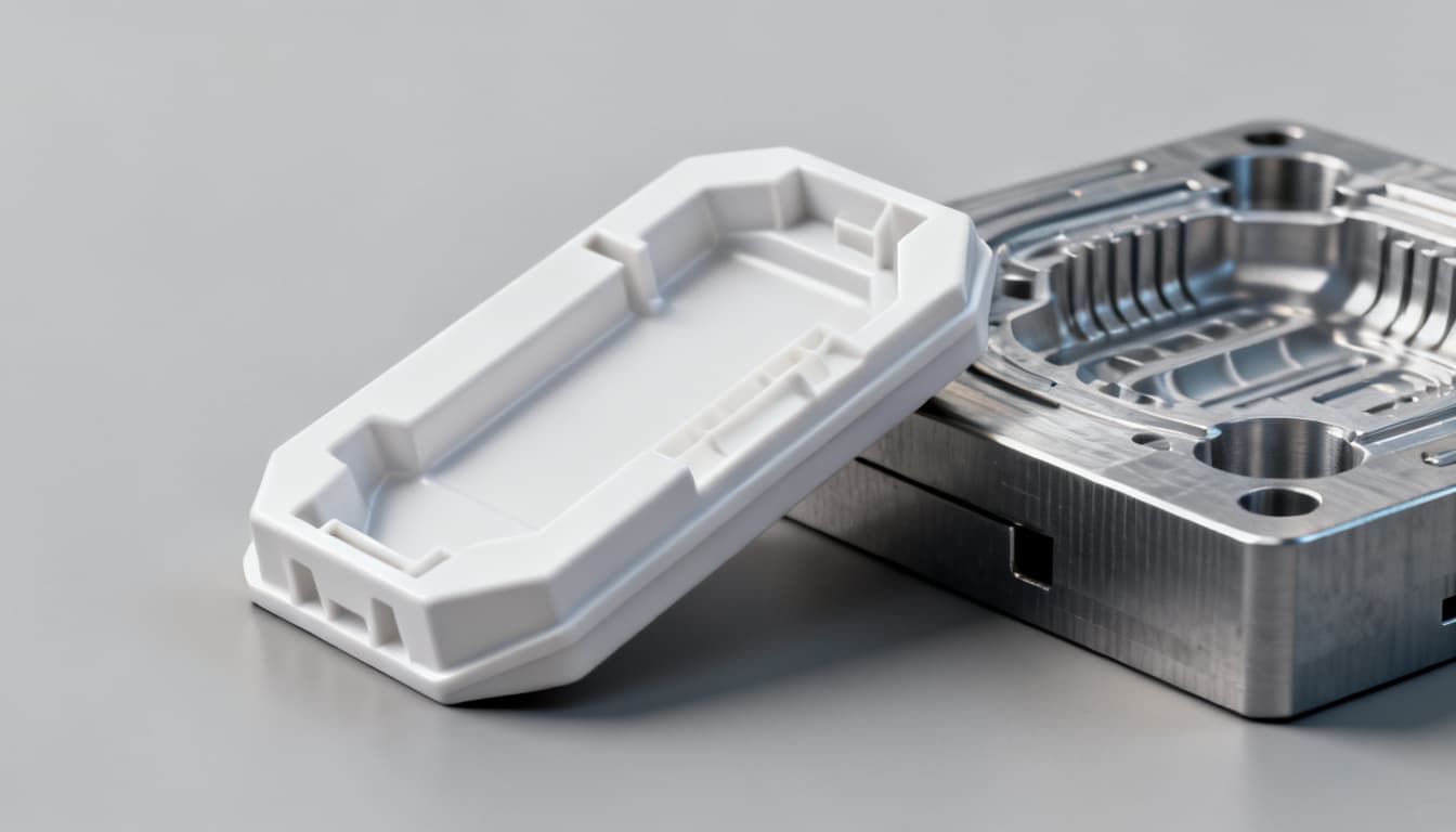
2026 Design for Injection Molding: New Best Practices for Tolerances, Draft, and Wall Thickness
Last year, a consumer electronics team lost six weeks and $28,000 in tool rework because they specified a deep leather-grain texture on a cosmetic housing without adjusting the draft angle. The result: drag marks across every A-surface, sticking during ejection, and a mold that had to go back to the
Why 2026 Demands a Fresh Look at Injection Molding Design Rules
Last year, a consumer electronics team lost six weeks and $28,000 in tool rework because they specified a deep leather-grain texture on a cosmetic housing without adjusting the draft angle. The result: drag marks across every A-surface, sticking during ejection, and a mold that had to go back to the bench for re-texturing and polishing. It's a failure mode that seasoned molders see repeatedly—insufficient draft angles causing sticking, drag marks, and excessive friction, especially on textured surfaces—and it's exactly the kind of oversight that hits harder in 2026 than it did five years ago.
Why now? Because NPI (New Product Introduction) cycles have compressed. Tooling lead times that once stretched to 14 weeks are now expected in 8. Supply chain disruptions mean fewer chances to iterate. A DFM (Design for Manufacturability) oversight that might have been caught in a second design review now lands directly on the production floor, where the cost of correction multiplies by a factor of ten. The fundamentals haven't changed—wall thickness, draft, and tolerances still govern part quality—but the margin for error has shrunk dramatically.
Core rules remain the starting point. Nominal wall thickness should stay between 1.2 mm and 3 mm for most engineering thermoplastics, with a baseline draft of 1° per inch of draw depth. Ribs must not exceed 60% of the adjacent wall thickness to avoid sink marks—reduce rib thickness to ≤60% of wall thickness, increase packing pressure and extend packing time, and locate the gate near thick sections so they pack effectively before the gate freezes. These aren't suggestions; they're physics. Yet in the rush to freeze CAD and release tooling, even experienced engineers cut corners on these basics.
What's different in 2026 is the expectation that design and manufacturing communicate earlier and more precisely. A holistic DFM approach—one that evaluates wall thickness, draft, and tolerances as an interdependent system rather than a checklist of isolated rules—is no longer a nice-to-have. It's the difference between a tool that runs lights-out and one that needs constant babysitting. The sections that follow unpack exactly how to get that system right.
Wall Thickness, Draft, and Tolerances: The Triad That Makes or Breaks Molded Parts
Ask any tooling engineer what separates a production-ready design from one that will fight you on every shot, and they'll point to the same three parameters: wall thickness, draft angle, and dimensional tolerance. These aren't independent variables. Change one, and the other two shift in response—sometimes subtly, sometimes catastrophically. Understanding how they interact is the foundation of injection molding DFM.
Wall thickness drives everything. It determines cooling time (which dominates cycle time), material consumption, and the part's ability to hold a dimension. Thinner walls cool faster, use less material, and cost less—but only when structural requirements allow. The sweet spot for most unfilled thermoplastics sits between 1.5 mm and 2.5 mm. Drop below 1.0 mm and flow resistance spikes; exceed 3.5 mm and you're adding seconds of cooling time per cycle while inviting sink marks and internal voids.
Draft angle is the parameter most likely to be treated as an afterthought—and the one most likely to cause tool rework when ignored. There is no single criterion for draft angle; it depends on depth, material, molding method, and surface finish. A polished ABS part with 25 mm of draw might release cleanly at 0.5° of draft. That same geometry with a molded-in texture could demand 5° or more. The rule of thumb—1° per inch of depth—is a starting point, not a finish line.
Tolerances tie the system together. Uniform wall thickness, balanced flow, and proper draft all improve dimensional stability. When walls vary in thickness, differential cooling creates residual stress that pulls features out of spec. When draft is insufficient, ejection forces distort the part before it has fully solidified. The table below captures the practical ranges engineers should work within for each parameter across common material families.
| Parameter | Unfilled Thermoplastics (ABS, PC, PA) | Glass-Filled Resins (PA-GF30, PBT-GF) | Unit/Notes |
|---|---|---|---|
| Nominal wall thickness | 1.2 – 3.0 | 1.0 – 2.5 | mm; thinner possible with high-flow grades |
| Minimum wall thickness | 0.8 | 0.6 | mm; flow-length dependent |
| Rib thickness (max) | ≤60% of nominal wall | ≤50% of nominal wall | % of adjacent wall; higher shrink risk with filled resins |
| Base draft angle (polished) | 0.5° – 1.0° | 0.5° – 1.5° | Degrees; per side, depth-dependent |
| Draft for light texture (VDI 24–30) | 2.0° – 3.0° | 2.5° – 4.0° | Degrees; add 1° per 0.025 mm texture depth |
| Draft for heavy texture (VDI 36–42) | 4.0° – 6.0° | 5.0° – 7.0° | Degrees; leather grain and similar |
| Commercial tolerance (DIN 16901) | ±0.10 – ±0.30 | ±0.08 – ±0.25 | mm; size-dependent, see standard tables |
| Fine tolerance (achievable) | ±0.05 – ±0.10 | ±0.03 – ±0.08 | mm; requires process capability study |
| Gusset height (max) | ≤2× nominal wall | ≤2× nominal wall | Ratio; up to 4× feasible with caution |
| Texture clearance from parting line | ≥1.5 | ≥1.5 | mm; prevents drag marks and flash |
Key takeaway: The numbers in this table aren't theoretical limits—they're thresholds where defect rates begin to climb. A rib at 65% of wall thickness might produce acceptable parts on a well-tuned press with optimal gating. But at 70%, sink marks become statistically inevitable across a production run. The 60% rule exists because it works at scale, across thousands of shots, with normal process variation.
Material choice amplifies or dampens every parameter. Glass-filled resins shrink less and hold tighter tolerances than their unfilled counterparts, but they also demand more draft because they're stiffer and less forgiving during ejection. Amorphous resins like ABS and polycarbonate are more dimensionally stable than semi-crystalline materials like nylon or acetal, which shrink more and warp more predictably. These interactions are why mold engineers and product designers must work together on DFM before the mold project launches—not after the CAD is frozen.
Tolerance Standards Face-Off: DIN 16901 vs. ISO 20457 for Molded Parts
Every injection molding project eventually hits the tolerance conversation. The engineer wants ±0.05 mm on a critical bearing bore. The molder pushes back, citing tool wear and process capability. The buyer asks why the piece-part price just doubled. At the center of this negotiation sit two standards: DIN 16901 and ISO 20457. Knowing which one to reference—and what each actually delivers—can save thousands in tooling cost and months of back-and-forth.
DIN 16901 has been the workhorse tolerance standard for injection-molded plastic parts for decades, particularly in European and Asian supply chains. It defines tolerance classes based on part size and material shrinkage category, giving designers a graduated framework: tighter tolerances for small features, wider bands for large dimensions. ISO 20457, published more recently, builds on DIN 16901's foundation but adds broader international applicability and refined categories for modern engineering resins. In practice, many molders still quote from DIN 16901 tables while acknowledging ISO 20457 as the emerging global benchmark.
Wall thickness uniformity is one of the biggest contributors to dimensional stability, which directly determines whether a part can stay within a given tolerance band. A part with 2.0 mm nominal walls and a well-balanced fill pattern might hold ±0.08 mm on critical features. The same part with a 1.5 mm wall variation could drift to ±0.20 mm or worse, regardless of which standard you cite. The standard defines the target; the design determines whether you can hit it.
Cost is the other dimension. Tighter tolerances directly increase part cost through higher tooling precision requirements, longer cycle times (more cooling and packing), increased inspection burden, and higher scrap rates. A commercial-tolerance part might require only dimensional spot checks. A fine-tolerance part demands CMM inspection on every critical feature, often with SPC (Statistical Process Control) tracking across the production run. The comparison below helps designers decide which standard to invoke for which features.
| Comparison Metric | DIN 16901 | ISO 20457 | Selection Criteria & Failure Boundary |
|---|---|---|---|
| Scope | Injection-molded thermoplastics; established German standard | Broader plastics processes; international (ISO) framework | Use DIN 16901 for legacy European tooling; ISO 20457 for new global programs |
| Tolerance granularity | Multiple classes by size range and material shrinkage group | Refined classes with explicit process capability references | DIN 16901 offers more historical data; ISO 20457 aligns with modern SPC practices |
| Smallest achievable tolerance | ±0.05 mm for features under 10 mm (fine class, low-shrink materials) | ±0.02 mm under optimal conditions (documented by Boyan's practical guide) | ±0.02 mm requires process validation; not sustainable across high cavitation without regular tool maintenance |
| Industry adoption | Dominant in European automotive and industrial sectors | Growing adoption in medical, aerospace, and multinational programs | Check your molder's familiarity; quoting ISO 20457 to a shop that works exclusively in DIN 16901 creates confusion |
| Cost impact of tightest class | 20–40% premium over commercial tolerance | Comparable premium; may add documentation cost for ISO compliance | Reserve tightest classes for features affecting function, assembly, or sealing—never blanket-apply to entire part |
Practical guidance: For most commercial and industrial parts, DIN 16901 tolerance class "normal" or ISO 20457 class "M" (medium) delivers acceptable dimensional control without driving up cost. Reserve fine tolerances for bearing fits, seal surfaces, snap-fit features, and alignment bosses. On a typical housing with 30 dimensions, perhaps 5 genuinely need tight control. The other 25 can float within commercial bands without affecting function—and that's where the cost savings live.
One nuance worth flagging: both standards assume the part has been designed with uniform wall thickness and adequate draft. A part that violates those fundamentals will struggle to meet any tolerance class, regardless of what's on the print. The standard quantifies what's achievable under good design practice; it doesn't compensate for design deficiencies.
From Ribs to Textures: Practical Design Moves That Prevent Defects and Cut Costs
By the time a design reaches the DFM review stage, the big decisions—parting line location, gate type, material family—are usually locked. What remains are the dozens of small geometry decisions that determine whether the tool produces good parts from shot one or requires weeks of debugging. This section covers the highest-leverage moves engineers can make in the final design phase.
Ribs: thinner and more of them. The impulse to add a single thick rib for stiffness is understandable—it's simpler to model and looks cleaner in CAD. But ribs thicker than 60% of the nominal wall create a localized mass of material that cools slower than surrounding areas, producing sink marks on the opposite surface. The fix is counterintuitive but effective: use two or three thinner ribs spaced evenly instead of one thick one. The combined stiffness is comparable, and the sink risk drops dramatically. Gate placement matters too—locate the gate so the packing pressure reaches the rib root before the gate freezes, ensuring the rib is fully packed out.
Textures: draft first, texture second. Textured surfaces demand significantly more draft than polished ones. The rule of thumb is to add 1° of draft per 0.025 mm (0.001 inch) of texture depth on top of the base draft requirement. A light SPI/VDI texture with 0.025 mm depth needs about 1° extra. A deep leather grain at 0.10 mm depth needs at least 4° extra—plus the base 1–2° for the underlying geometry. That's 5–6° total, which can visibly alter part aesthetics if not accounted for early. Always request a texture draft analysis from the molder or texture supplier before cutting steel. The analysis maps exactly where the texture will drag and identifies surfaces that need additional draft.
Gussets: small features, big impact. Gusset height should not exceed 2 times the nominal wall thickness, though up to 4 times is feasible with careful design. Gussets stiffen corners and reduce warpage without adding significant mass, but oversized gussets create the same sink risk as oversized ribs. The 2× rule keeps the gusset's thermal mass low enough that it cools in sync with the surrounding wall.
Parting line awareness. One of the most expensive DFM mistakes is placing a texture, logo, or critical cosmetic surface too close to the parting line. Textured surfaces must stay at least 1.5 mm from any parting line to avoid drag marks during ejection and flash formation as the tool wears. A last-minute marketing request to add a logo near the parting line—without adjusting draft or position—is a reliable recipe for tool rework.
The table below consolidates these rules into a quick-reference format suitable for a pre-freeze DFM checklist.
| Design Feature | Best Practice | Common Failure Mode | Prevention / Verification |
|---|---|---|---|
| Rib thickness | ≤60% of nominal wall (≤50% for filled resins) | Sink marks on opposite surface | Cross-section review in DFM; gate near rib root |
| Rib spacing | ≥2× nominal wall between ribs | Thin steel sections in tool; cooling challenges | Tool steel feasibility check with molder |
| Gusset height | ≤2× nominal wall (4× max with caution) | Sink at gusset base; warpage if undersized | Mold flow analysis on large gussets |
| Texture draft | Base draft + 1° per 0.025 mm texture depth | Drag marks, sticking, ejection damage | Texture draft analysis before tool steel cut |
| Texture-to-parting-line clearance | ≥1.5 mm | Flash, drag marks, premature tool wear | CAD measurement; DFM review checklist |
| Wall thickness transitions | Gradual; 3:1 max thickness ratio at transitions | Flow hesitation, weld lines, warpage | Mold flow simulation; sectional thickness map |
| Boss OD for self-tapping screws | 2.0–2.5× screw diameter | Boss cracking, insufficient hoop strength | Boss design calculator; material-specific guidelines |
| Corner radii (internal) | ≥0.5× nominal wall thickness | Stress concentration, cracking under load | FEA on load-bearing corners |
Tip: Before freezing CAD, run through a simple self-audit: (1) Are all walls within 20% of the nominal thickness? (2) Does every surface that contacts the mold have draft—including ribs, bosses, and snap features? (3) Are tight tolerances applied only to features that genuinely need them? (4) Is every texture at least 1.5 mm from the parting line? A "no" to any of these questions warrants a conversation with your molder before the tool steel order goes out.
A structured DFM checklist before freezing CAD catches most of the issues that would otherwise surface during tool tryout—when corrections are exponentially more expensive. The best molders will provide this analysis as part of their quoting process. If yours doesn't, ask for it.
Design for Injection Molding FAQ: Answers Engineers and Buyers Actually Need
The following questions come directly from product engineers and sourcing managers who manage injection molding programs day to day. The answers reflect the best practices covered in this article, condensed for quick reference.
Q: How do I balance wall thickness for strength without causing sink marks?
Keep nominal walls between 1.2 mm and 3.0 mm, and limit ribs to ≤60% of the adjacent wall thickness (≤50% for glass-filled resins). If a single rib doesn't provide enough stiffness, use multiple thinner ribs spaced at least twice the nominal wall thickness apart rather than one thick rib. Gate placement is equally important—position the gate so packing pressure reaches thick sections and rib roots before the gate freezes. A mold flow simulation will confirm whether your gate location delivers adequate packing to critical features. For parts with unavoidable thick sections, consider coring out material from the back side to maintain uniform wall thickness while preserving the external geometry.
Q: What draft angle do I need for a deep textured cosmetic surface?
Start with 1° of additional draft per 0.025 mm (0.001 inch) of texture depth, added to the base draft requirement for the underlying geometry (typically 1–2° for polished surfaces). A deep leather grain with 0.10 mm texture depth therefore needs at least 5° of total draft per side—1° base plus 4° for the texture. For very deep textures (VDI 36–42 or equivalent), 6–7° may be necessary. Always request a texture draft analysis from your molder or texture supplier before tool steel is cut. This analysis maps the exact draft angle on every textured surface and identifies areas where the texture will drag or scuff during ejection. Adjusting draft in CAD is inexpensive; re-texturing a tool after it's built is not.
Q: When does it make sense to pay for tighter tolerances?
Only on features that directly affect function, assembly, or sealing. Bearing bores, snap-fit engagement surfaces, seal grooves, and alignment features typically justify fine tolerances. Cosmetic surfaces, non-functional ribs, and clearance features do not. Use DIN 16901 or ISO 20457 to define tolerance classes for critical dimensions, and leave everything else at commercial (normal/medium) tolerance. Tighter tolerances increase tooling cost (higher-precision machining, tighter process control), cycle time (longer packing and cooling), and inspection burden (CMM measurement, SPC tracking). On a typical housing, perhaps 5 out of 30 dimensions genuinely need tight control. Applying fine tolerances to all 30 can double the piece-part price with no functional benefit.
Q: Can I avoid warpage in large flat parts by adding ribs alone?
Ribs help but are not a standalone solution. The first and most effective defense against warpage is uniform wall thickness combined with balanced filling. Differential cooling—where thick sections cool slower than thin ones—is the primary driver of warpage in injection-molded parts. Ribs can stiffen a flat surface, but if they're too thick (over 60% of nominal wall), they introduce sink marks and can actually worsen warpage by creating localized shrinkage differentials. Use gussets at corners (height ≤2× nominal wall thickness) to add stiffness without adding mass. Material choice also matters significantly: glass-filled resins shrink less and warp less than unfilled grades. A 30% glass-filled nylon will hold flatness far better than unfilled nylon or polypropylene in a large, flat geometry. Run a mold flow warpage analysis before finalizing the design—it will show you exactly where distortion is likely to occur and whether ribs, gussets, or material changes will solve it.
Q: What's the one DFM mistake that still surprises experienced designers?
Ignoring the parting line when placing textures, logos, or cosmetic features. Textured surfaces must stay at least 1.5 mm from the parting line to avoid drag marks during ejection and flash formation as the tool wears. A last-minute request to add a logo or texture near the parting line—without adjusting draft or position—is one of the most common causes of tool rework. The fix often requires welding and re-cutting the tool steel, or in severe cases, building a new cavity insert. The cost and delay are entirely avoidable with a simple parting line clearance check during the DFM review. If a feature absolutely must be near the parting line, discuss it with your molder before freezing the design—there are sometimes workarounds, but they need to be designed in, not patched in after the fact.
References & Further Reading
- Optimizing Design for Injection Molding: 6 Key Considerations — H&H Molds
- Injection Molding Design Guide in 2026: DFM Principles for Quality Parts — Weilin Plastic
- Injection Molding Guide 2026: Process, Design, Materials, Cost & Defects — PlasticMoulds
- Injection Molding Design Guide: Best Practices for Molded Plastic Parts — Fictiv
- Injection Molding Wall Thickness Guidelines and Design Specifications — TDL Mould
- Injection Molding Tolerances: DIN 16901, ISO 20457, and Practical Guidelines — Boyan Manufacturing Solutions
Want to discuss your project?
Use the quick bar below or this form—we will route you to an engineer.
Contact us