Cost Optimization Strategies for Automotive Injection Molding Service: Reducing Cycle Time Without Sacrificing Tolerance
Automotive programs are under relentless pressure to cut piece-part costs while holding dimensional tolerances that directly affect fit, finish, and long-term durability. OEMs and Tier-1 buyers routinely demand annual price reductions, yet the same parts must survive thermal cycling, vibration, and
Why Automotive Injection Molding Margins Are Compressed and Where Cycle Time Fits
Automotive programs are under relentless pressure to cut piece-part costs while holding dimensional tolerances that directly affect fit, finish, and long-term durability. OEMs and Tier-1 buyers routinely demand annual price reductions, yet the same parts must survive thermal cycling, vibration, and chemical exposure without warping or rattling. In this environment, the injection molding supply chain has already squeezed material pricing and tooling amortization. The next meaningful lever—and the one that often determines whether a program stays profitable—is cycle time.
Cycle time is the single largest cost driver after raw material. Shaving even two seconds from a 45-second cycle on a high-volume automotive part can reduce piece price by 3–5% and free up press capacity worth hundreds of thousands of dollars annually. The challenge is that automotive tolerances are unforgiving. A door panel clip tower that drifts 0.15 mm can cause squeak-and-rattle issues; a glass-filled nylon bracket that warps out of flatness can fail assembly. So the question isn’t simply “how fast can we run,” but “how fast can we run without sacrificing the dimensional stability that the vehicle demands.”
Forward-thinking molders and their customers are answering that question by combining lean design-for-manufacturability (DFM) analysis with advanced tooling technology. For example, implementing valve-gated hot runner systems and optimizing the runner layout can cut material waste by up to 30% (LSRPF), simultaneously reducing cycle time because there’s no cold runner to cool and eject. Equally important, high-volume automotive production demands scientific process control—not just tweaking barrel temperatures—to lock in a robust process window that keeps critical dimensions centered between specification limits, shot after shot.
Key Takeaway: In automotive injection molding, cycle time reduction isn’t about running the press faster; it’s about engineering the mold, the material, and the process so that every second of the cycle contributes to a dimensionally stable part. When done right, the margin gains are substantial and repeatable.
How Cycle Time, Tolerance, and Process Stability Interact in Automotive Molds
To reduce cycle time without sacrificing tolerance, you first need to understand where the seconds go and how each phase of the molding cycle influences part dimensions. A typical automotive injection molding cycle breaks down into four phases: injection (filling), pack/hold, cooling, and ejection. Cooling typically consumes 50–70% of the total cycle, and it’s the phase most sensitive to tolerance because it governs how the polymer solidifies and shrinks.
Injection speed affects fill pressure and shear heating, which can shift melt viscosity and alter the way the material packs into the cavity. The pack/hold phase compensates for volumetric shrinkage; too short a hold time and the part sinks or voids, too long and you waste seconds without improving dimensions. Cooling time must be long enough for the part to reach a temperature below the material’s heat deflection point, but every extra second adds cost. Ejection is usually the shortest phase, yet improper ejection can warp a part that was perfectly molded.
Scientific molding principles (Zetar Mold) provide the foundation for stabilizing this interplay. By performing in-mold rheology studies, gate freeze tests, and pressure loss analyses, you establish a process window where fill, pack, and cooling are balanced to deliver consistent part weight and dimensions. Once that window is defined, you can systematically challenge each phase to find the minimum time that still yields a Cpk of 1.33 or higher on critical-to-function features.
The table below compares typical cycle time splits for two common automotive materials—a polypropylene (PP) interior trim component and a glass-fiber-reinforced nylon under-hood part. It highlights where seconds can often be removed without shifting dimensions beyond tolerance.
| Cycle Phase | PP Interior Trim (e.g., door insert) Typical Time (s) | PA66-GF30 Under-Hood Part Typical Time (s) | Tolerance Sensitivity & Optimization Potential |
|---|---|---|---|
| Injection (Fill) | 2.5 – 3.5 | 3.0 – 4.5 | High shear can cause flash or short shots. High-flow grades can reduce fill time by 10–15% without affecting dimensions. |
| Pack / Hold | 4.0 – 6.0 | 5.0 – 8.0 | Directly controls shrinkage and sink. Gate freeze study often reveals 1–2 seconds of overpacking that can be eliminated. |
| Cooling | 18.0 – 24.0 | 28.0 – 38.0 | Largest time block. Conformal cooling can reduce this by 20–40% while improving flatness and reducing warpage. |
| Ejection / Mold Open | 3.0 – 4.0 | 4.0 – 5.5 | Low sensitivity if ejection is balanced. Optimizing clamp motion and robotics can save 0.5–1.0 s. |
| Total Cycle | 27.5 – 37.5 | 40.0 – 56.0 | 10–20% reduction achievable through cooling and pack optimization alone, validated by dimensional capability studies. |
The numbers make clear that cooling time is the primary target. But reducing cooling time without a corresponding adjustment to mold temperature control can increase part warpage and dimensional scatter. That’s why the next section examines tooling choices that fundamentally change the thermal and material-flow dynamics of the mold.
Hot Runner vs. Cold Runner: Which System Delivers Lower Cost Per Part in High-Volume Automotive Programs?
For programs running 100,000 parts per year or more, the choice between a cold runner and a valve-gated hot runner system is often the single biggest factor in total cost of ownership. Cold runner molds are cheaper to build and maintain, but they generate a solidified runner that must be reground or scrapped, extend cycle time because the runner must cool alongside the part, and introduce gate vestige that can interfere with assembly. Hot runner systems eliminate the runner scrap, reduce cooling time, and enable sequential valve gating that improves flow balance and dimensional consistency across multi-cavity tools.
Lean DFM analyses that optimize the runner system can lower material waste by up to 30% (LSRPF). That alone often justifies the higher upfront tooling cost for a hot runner. However, the decision must also account for maintenance burden: hot runner systems contain heaters, thermocouples, and valve pins that require periodic servicing, and any downtime on a high-volume automotive line is expensive. Cold runners, while simpler, demand regrind handling and can suffer from runner imbalance that causes cavity-to-cavity dimensional variation.
The comparison table below helps buyers evaluate which system delivers the lower cost per part when tolerances and production scale are non-negotiable.
| Comparison Metric | Valve-Gated Hot Runner | Cold Runner (Conventional) | Selection Criteria & Failure Boundary |
|---|---|---|---|
| Upfront Tooling Cost | 25–60% higher than cold runner; complex geometries with multiple sliders amplify this (Ulite) | Lower initial investment, simpler design | Justifiable when annual volume exceeds 100k units and material cost is high. Below 50k units, cold runner often wins on total cost. |
| Cycle Time Impact | Reduces cycle by 15–25% because no runner cooling time; faster ejection | Longer cycle due to runner mass; cooling time extended | Critical for parts with thick walls where cooling dominates. Hot runner can free up press capacity. |
| Material Waste | Near-zero runner scrap; up to 30% material savings (LSRPF) | Runner scrap can be 20–40% of shot weight; regrind may degrade properties | High-cost engineering resins (e.g., PPS, PEEK) strongly favor hot runner. PP regrind is more forgiving. |
| Maintenance Burden | Higher: heaters, thermocouples, valve pins need periodic replacement; downtime risk | Lower: no active components in runner system; easier to clean | Hot runner maintenance must be factored into OEE. Redundant heater circuits reduce risk. |
| Tolerance Capability | Excellent gate vestige control; sequential gating reduces warpage and improves flatness | Gate vestige can vary; runner imbalance may cause cavity-to-cavity dimensional drift | For tight flatness specs or multi-cavity tools, hot runner provides superior process consistency. |
For a typical glass-filled nylon under-hood bracket produced at 200,000 units per year, switching from a cold runner to a valve-gated hot runner often pays back the tooling premium in 6–12 months through material savings and faster cycles. The key is to validate that the hot runner’s thermal profile doesn’t degrade the material—some glass-filled resins are sensitive to residence time at elevated temperatures—and to design the manifold so that all cavities fill within a 0.1-second window to maintain dimensional uniformity.
Design-for-Manufacturability Moves That Cut Seconds Without Compromising Part Function
Cycle time reduction doesn’t start on the molding floor; it starts in the CAD model. Product engineers who apply DFM principles early can eliminate features that force the mold to run slower, while preserving—or even improving—part performance. The following strategies have been proven across hundreds of automotive programs to deliver measurable cycle time savings without pushing tolerances out of spec.
Uniform wall thickness. Variations in wall thickness create hot spots that extend cooling time and cause differential shrinkage leading to warpage. Targeting a nominal wall of 2.5–3.0 mm for interior trim and 2.0–2.5 mm for structural brackets, with gradual transitions and generous radii, can reduce cooling time by 15–20% compared to a design with abrupt thickness changes. Use mold flow analysis to identify and core out thick sections.
Eliminate unnecessary undercuts. Every lifter or slider adds moving components that increase mold cost by 25–60% and extend lead times by 30–50% (Ulite). More importantly, these mechanisms slow down ejection and introduce maintenance downtime. Redesigning snap features to use pass-through cores or simple side actions can shave 1–2 seconds from the cycle while improving tool reliability.
Optimize gate location and size. A gate that is too small restricts flow, requiring higher injection pressure and longer fill time, which can also freeze off prematurely and cause sink. A gate that is too large leaves a vestige that may need trimming. Placing the gate in the thickest section and sizing it for the material’s recommended shear rate ensures fast, balanced filling. For glass-filled materials, a fan gate or a valve gate that opens sequentially can minimize fiber orientation warpage.
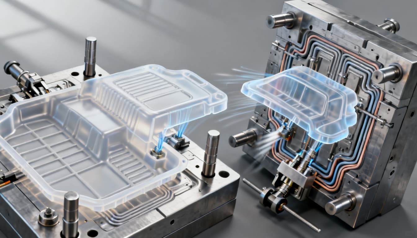
Leverage conformal cooling. When cycle time is bottlenecked by cooling and the part has deep cores or thick bosses, conformal cooling channels that follow the part contour can reduce cooling time by 20–40%. Additive-manufactured inserts make this feasible even for medium-volume programs, and the tooling premium is often recovered within the first year of production.
Refining machine settings and cooling times directly lowers the overall cycle time per part (Thogus). However, these changes must be made within a validated process window. Use cost calculation methods (SWCPU) to quantify the savings from each second removed, and always confirm that the new cycle produces parts with a stable Cpk on the dimensions that matter most to the vehicle assembly.
The table below summarizes common DFM moves and their typical impact on cycle time, tooling cost, and tolerance risk.
| DFM Action | Typical Cycle Time Reduction | Effect on Tooling Cost | Tolerance Risk & Mitigation |
|---|---|---|---|
| Uniform wall thickness (2.5 mm ±0.2 mm) | 15–20% cooling time reduction | Neutral; may reduce steel mass | Lower warpage risk; validate with mold flow |
| Replace lifters with pass-through cores | 1–2 s per cycle | Reduces mold complexity, saving 10–15% | Eliminates moving component wear; no tolerance penalty |
| Optimize gate size & location | 0.5–1.5 s fill time reduction | Minimal | Improves filling balance; verify with short-shot study |
| Conformal cooling inserts | 20–40% cooling time reduction | Adds 15–25% to insert cost | Reduces warpage and improves flatness; validate thermal uniformity |
| Switch to high-flow material grade | 10–15% fill time reduction | No tooling change | Must meet OEM material spec and heat aging requirements |
Each of these moves requires collaboration between the product engineer, the mold designer, and the molder. The goal is a mold that runs at its natural, stable limit—not a pushed cycle that drifts out of tolerance after a few thousand shots.
Automotive Injection Molding Cost Reduction FAQ: What Senior Engineers and Buyers Ask
When a molder proposes to reduce cycle time without affecting tolerance, experienced buyers and engineering managers ask pointed questions. Below are the answers that separate credible, data-driven proposals from wishful thinking.
- Q: How much cycle time reduction is realistic without affecting critical dimensions on an automotive part?
- Typically 10–20% through optimized cooling and packing phases alone. Greater gains require DFM changes or hot-runner conversion. Any change must be validated with process capability studies (Cpk) on the dimensions that matter most—usually the datums that control fit to mating components. A 15% reduction is a solid, defensible target for a well-designed mold running a stable process.
- Q: What’s the payback period for converting a cold runner mold to a valve-gated hot runner system?
- For programs above 100,000 parts per year, payback often falls within 6–12 months, driven by material savings (up to 30% less waste) and faster cycles. The exact figure depends on resin price and press rate. For example, a glass-filled nylon part with a $4.50/kg material cost and a press rate of $45/hour can see a payback in under 9 months. Always run a total-cost-of-ownership model that includes maintenance and downtime risk.
- Q: Can conformal cooling be justified for medium-volume automotive programs?
- Yes, when cycle time is the bottleneck and the part has thick sections or tight flatness specs. Additive-manufactured inserts can reduce cooling time by 20–40%, and the tooling premium is often recovered within the first year of production. For volumes of 50,000–100,000 units/year, the business case hinges on the value of freed-up press capacity and reduced scrap from warpage.
- Q: How do I verify that a molder’s cycle time claims won’t degrade long-term tolerance?
- Require a production-intent process window study and a 24-hour continuous run with dimensional checks at startup, mid-run, and end. Look at cavity-to-cavity variation and stability of critical-to-function features, not just average dimensions. A capable process should maintain Cpk ≥ 1.33 on all key characteristics throughout the run, with no drift beyond the control limits.
- Q: What role does material selection play in reducing cycle time while keeping mechanical properties?
- High-flow grades of the same polymer can fill faster and pack at lower pressures, shaving seconds. Nucleated or fast-crystallizing variants (e.g., PP, PA) reduce cooling time because they solidify more quickly. Always confirm that the alternative meets the OEM’s material specification and long-term heat aging requirements—a faster cycle is worthless if the part fails at 1,000 hours of thermal exposure.
- Q: Is it possible to renegotiate piece price after tooling is built if cycle time improves?
- Yes, many automotive supply agreements include continuous improvement clauses. Document the baseline cycle time and tolerance capability at PPAP, then propose a price adjustment tied to verified, sustained cycle time reductions—sharing a portion of the savings keeps the relationship productive. A common model is a 50/50 split of the documented cost reduction for the first year, transitioning to full savings for the buyer thereafter.
These answers reflect the reality that cycle time optimization in automotive injection molding is a collaborative, data-intensive effort. It’s not about pushing a machine to its limit; it’s about engineering every aspect of the mold, material, and process to run faster while staying within the dimensional envelope the vehicle requires.
References & Further Reading
- Automotive Plastic Injection Molding Service: OEM Vehicle Parts Cost-Effective DFM Guide – LSRPF
- Strategies for Injection Molding Cost Reduction – Thogus
- Cost Optimization Strategies for Efficient Injection Molding – Zetar Mold
- Efficient Injection Molding Cost Breakdown and Optimization 8 Strategies – SWCPU
- 5 Ways to Reduce Injection Molding Costs Through Design Optimization – Ulite
- Understanding Injection Molding Cost for Manufacturers – Xometry
Ready to apply these strategies to your next automotive program? Our team at PandaMolding combines deep DFM expertise with advanced molding technology to help you reduce cycle time without compromising tolerance. Contact us today to discuss your project and get a quote.