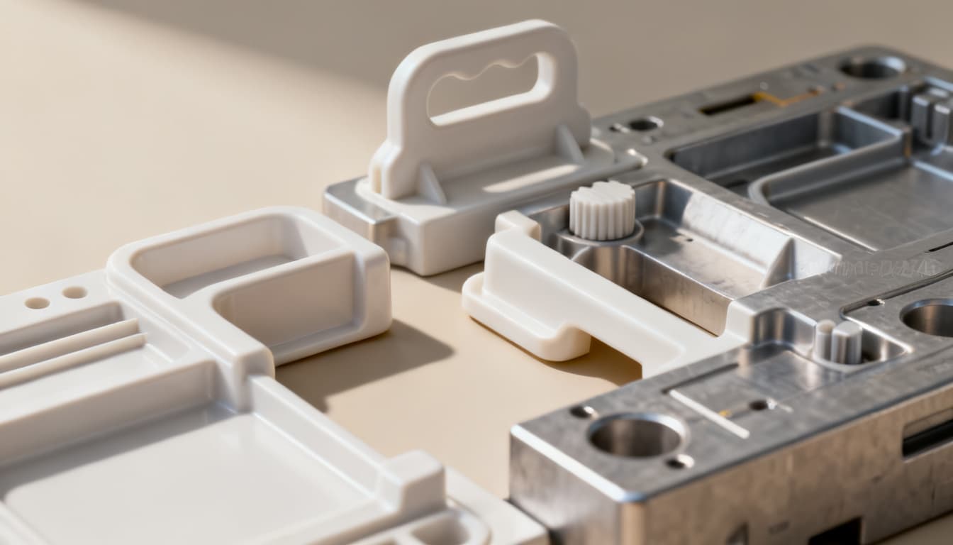
Designing Safe Plastic Components: 5 Common Mistakes That Compromise Child Safety and How to Avoid Them
When a plastic toy fractures into sharp shards or a baby bottle component detaches into a choke-sized fragment, the failure mode was almost certainly designed in months earlier—at the CAD workstation, not on the factory floor. The past twelve months have reinforced a hard truth: poor design choices
Why Child Safety in Plastic Components Demands a Zero-Failure Mindset
When a plastic toy fractures into sharp shards or a baby bottle component detaches into a choke-sized fragment, the failure mode was almost certainly designed in months earlier—at the CAD workstation, not on the factory floor. The past twelve months have reinforced a hard truth: poor design choices in injection-molded components don't just compromise durability or cost-efficiency; they create direct pathways to child injury. As industry observers at Aaamould have noted, design flaws compromise safety, durability, and cost-efficiency simultaneously—brittle parts, unexpected fractures, and expensive recalls are symptoms of decisions made long before tool steel is cut.
What makes child-safety engineering uniquely demanding is the absence of graceful degradation. An automotive interior panel that cracks at a stress riser is a warranty claim. A teething toy that cracks at that same stress riser is a choking hazard, a laceration risk, and potentially a product-liability catastrophe. The Society of Plastics Engineers has long emphasized that systematic failure analysis is the most efficient and effective approach to preventing plastic component failure. For products destined for children's hands—and mouths—that analysis must begin at the concept stage, not after a recall letter is drafted.
The zero-failure mindset isn't aspirational; it's a design constraint as real as draft angles and cycle times. Every snap-fit, every boss, every wall-thickness transition represents a decision point where child safety is either preserved or quietly compromised. The five mistakes explored in this article are the ones our engineering teams at PandaMolding encounter most frequently when reviewing part designs from clients who've experienced near-misses or field failures. None of them require exotic materials or prohibitive tooling budgets to fix. What they demand is awareness, applied early, before the first prototype leaves the printer.
The Engineering Baseline for Child-Safe Plastic Parts
Before examining specific failure modes, engineers need a shared reference frame for what "child-safe" means at the material and geometry level. Three principles govern every decision: the material must resist impact fracture without producing sharp edges; the geometry must eliminate features small enough to detach and obstruct an airway; and the structural design must distribute stress so that no single point becomes a predictable fracture origin. These principles are interdependent—a ductile material in a poorly radiused geometry can still snap, and a well-radiused part in a brittle grade can still shatter.
Material selection sits at the foundation. The checklist for preventing design pitfalls developed through academic-industry collaboration underscores that material choice cannot be separated from geometry—the two must be evaluated together during the design review. A polymer that performs beautifully in a uniform-thickness test coupon may fail catastrophically when molded into a complex geometry with abrupt section changes. Similarly, the essential guidelines for plastic part design emphasize that engineers who overlook the material-geometry interaction often face part failures, quality issues, and costly revisions that could have been prevented with early analysis.
Rib and boss design principles, originally codified for automotive components but universally applicable, provide a useful starting framework. The guidelines for nominal wall thickness, ribs, undercuts, holes, bosses, and flanges developed for automotive injection molding translate directly to consumer products—the physics of polymer flow and stress distribution don't change when the end user is a toddler. What changes is the consequence of getting it wrong.
Tip: When evaluating materials for child-contact applications, request the full migration test data from your resin supplier—not just the datasheet values. A material that passes food-contact certification at 23°C may behave differently at the elevated temperatures of dishwasher sterilization or prolonged mouthing.
| Material | Notched Izod Impact (J/m) | Child-Safety Suitability | Typical Applications | Key Limitations |
|---|---|---|---|---|
| Polypropylene (PP) | 27–107 (varies by grade) | Excellent—inherently ductile, BPA-free, low density | Teething rings, bottle caps, toy hinges | Lower stiffness; UV degradation without stabilizers |
| High-Density Polyethylene (HDPE) | 21–214 | Excellent—chemically inert, no plasticizers | Bath toys, squeeze bottles, outdoor play equipment | Poor paint adhesion; waxy surface limits bonding |
| ABS (BPA-free grades) | 107–320 | Good—high impact strength, rigid; must specify BPA-free | Toy housings, building blocks, protective shells | Verify BPA-free certification per lot; solvent sensitivity |
| Polycarbonate (PC) | 640–850 | Limited—exceptional impact strength but BPA concerns | Historically baby bottles; now largely replaced | BPA migration risk; use only co-polyester alternatives for oral contact |
| Co-polyester (Tritan™, Eastar™) | 100–650 (no break on some grades) | Excellent—BPA-free, high clarity, dishwasher-safe | Baby bottles, sippy cups, transparent toy components | Higher material cost; longer cooling cycles |
| TPE/TPU (overmolding grades) | No break (flexible) | Good—soft-touch, no sharp fracture edges | Grips, teething surfaces, soft-touch overmolds | Must verify plasticizer-free grades; compression set over time |
The table above reflects real trade-offs, not theoretical ideals. Polypropylene and HDPE dominate the child-product landscape for good reason: they're inherently ductile, free of bisphenol-A chemistry, and forgiving in thin-wall molding. ABS offers superior surface finish and rigidity but demands careful grade selection—not all ABS resins are created equal where endocrine-disrupting chemistry is concerned. Polycarbonate, despite its legendary impact resistance, has largely exited the infant and toddler market due to BPA migration concerns, replaced by co-polyester alternatives that deliver comparable clarity without the regulatory baggage.
Beyond material chemistry, geometry drives safety outcomes. Every internal corner below 0.5 mm radius is a stress concentrator waiting to initiate a crack. Every boss designed without consideration for how it might fail—and what size fragment it would produce—is a potential choking hazard. The engineering baseline isn't a checklist; it's a discipline of asking, at every design review, "How does this feature behave when it breaks?"
5 Design Mistakes That Put Children at Risk—and How to Avoid Them
The following five mistakes recur across industries, geographies, and product categories. They share a common thread: each is invisible in a CAD rendering, undetectable in a quick visual inspection, and entirely preventable with the right design discipline applied early.
Mistake 1: Sharp Internal Corners and Insufficient Radii
The most common stress-riser in injection-molded parts is also the easiest to fix—and the most frequently overlooked. When a part features a sharp internal corner where two walls meet, the stress concentration factor can exceed 3.0, meaning the local stress is triple the nominal value. Under impact loading—a toy dropped onto hardwood, a bottle flung from a high chair—that corner becomes the fracture origin. The resulting shards are typically sharp-edged triangles, precisely the geometry most dangerous to a child's skin and mouth.
Fix: Apply a minimum internal radius of 0.5 mm to every corner, with 1.0 mm preferred wherever geometry permits. For external edges, radius to at least 1.0 mm. Use variable-radius fillets where space is constrained, blending from a larger radius at the base to a smaller one at the apex. Run a mold-filling simulation to verify that the radiused geometry doesn't create unexpected knit lines or flow hesitations.
Mistake 2: Incorrect Rib Placement and Oversized Bosses
Ribs and bosses are essential for stiffness and assembly, but they're also the features most likely to create dangerous failure modes. As Ensinger Precision Components has documented, incorrect rib placement or oversized bosses can create stress concentration points and make the part more susceptible to failure. The problem compounds when multiple ribs intersect at a single boss, creating a thick material mass that cools unevenly, develops sink marks, and concentrates stress at the boss base.
For child-safety applications, the boss failure mode deserves special scrutiny. A boss that snaps off cleanly at its base can produce a cylindrical fragment small enough to lodge in a child's throat. The small-parts cylinder test (simulating a child's airway at 31.7 mm diameter by 57.1 mm depth) should be applied to every boss geometry: if the detached boss fits entirely within that cylinder, it's a choking hazard by definition.
Fix: Keep rib thickness to 50–60% of the adjacent nominal wall. Design bosses with generous root radii and consider adding gussets that tether the boss to adjacent walls, ensuring that even if fracture occurs, the fragment remains attached. For snap-fit bosses, incorporate breakaway zones that fail in a ductile, hinging mode rather than a brittle snap. Orient ribs perpendicular to the melt flow front to minimize sink and ensure uniform packing.
Mistake 3: Uneven Wall Thickness and Sink-Induced Weak Points
Wall thickness variations create differential cooling rates. The thick sections remain molten while thin sections have already solidified, generating internal stresses that manifest as sink marks on the surface and residual stress through the cross-section. In a child's product subjected to repeated impact and flexural loading, those sink marks aren't cosmetic defects—they're fatigue initiation sites.
Fix: Maintain nominal wall thickness between 1.5 mm and 3.0 mm for most child-product geometries. Where thickness transitions are unavoidable, use a gradual taper over a distance of at least 3× the thickness difference. Avoid abrupt step changes. Core out thick sections rather than leaving them solid—a hollow ribbed structure is both lighter and tougher than a solid block of the same external dimensions. Use mold-flow analysis to identify and eliminate hesitation effects and uneven filling patterns before cutting steel.
Mistake 4: Material Selection Without Verifying Impact and Toxicity for Child Exposure
Selecting a polymer based solely on its room-temperature datasheet properties is a gamble when the application involves prolonged oral contact, dishwasher sterilization, or UV exposure in outdoor play equipment. A material that passes Izod impact testing at 23°C may become brittle at the 0°C temperatures of a winter playground. A resin certified as food-contact-safe for adults may not have been evaluated for the elevated exposure scenarios relevant to toddlers who mouth objects for hours daily.
Fix: Specify impact testing at the full range of service temperatures, including cold-conditioning at -10°C for outdoor toys. Request migration testing data specific to the intended use scenario—prolonged oral contact, repeated dishwashing, or UV aging. For any component intended for mouthing by children under 3, restrict material selection to PP, HDPE, or certified BPA-free co-polyester grades. Document the resin grade, lot number, and certification in the production record for traceability.
Mistake 5: Skipping Rigorous Testing and Validation Before Production
The pressure to hit launch deadlines creates a temptation to compress the validation phase—running a few drop tests on 3D-printed prototypes and calling it done. But FDM or SLA prototypes don't replicate the anisotropic properties, knit-line behavior, or residual stress state of an injection-molded part. As Expertia's engineering resources note, the most effective safeguard is to implement rigorous testing and validation protocols to catch issues before they reach production, with regular audits of the manufacturing process identifying potential issues early enough to prevent costly recalls.
Fix: Build a validation sequence that includes: (1) mold-flow analysis on the stable 3D CAD model to predict knit lines, sink marks, and high-stress regions; (2) accelerated life testing on production-intent prototypes molded in the specified material from a prototype tool or bridge tool; (3) small-parts cylinder testing on every detachable or breakable feature; (4) drop testing at multiple orientations and temperatures; and (5) production-process auditing at statistically meaningful intervals during the first production run. The cost of this sequence is a fraction of a single recall.
| Mistake | Failure Mode | Child-Safety Consequence | Design Rule of Thumb | Verification Method |
|---|---|---|---|---|
| Sharp internal corners | Stress concentration >3× nominal | Sharp shards on fracture; laceration hazard | Min. 0.5 mm internal radius; 1.0 mm external | FEA stress analysis; drop-test fracture inspection |
| Oversized bosses / poor rib placement | Brittle boss detachment; stress at rib intersections | Choking hazard from detached cylindrical fragment | Rib thickness ≤60% of wall; gusset-tether bosses | Small-parts cylinder test; pull-force-to-failure |
| Uneven wall thickness | Differential cooling; sink marks; residual stress | Fatigue crack initiation at sink locations | 1.5–3.0 mm nominal; 3:1 taper ratio for transitions | Mold-flow simulation; cross-section analysis |
| Unverified material for child exposure | Low-temperature embrittlement; chemical migration | Toxic exposure; unexpected brittle fracture | Test at full service temperature range; verify migration data | Cold-conditioned impact testing; migration lab report |
| Skipped validation testing | Undetected knit lines; anisotropic weakness | Field failures discovered by end users | Production-intent prototypes; parallel testing paths | Accelerated life testing; production audit sampling |
These five mistakes rarely occur in isolation. A part with sharp internal corners often also has uneven wall thickness. A team that skips validation testing is likely the same team that didn't verify material certifications. The common root cause is treating child-safety requirements as a compliance checkbox rather than an engineering constraint integrated into every design decision from concept through production.
Child-Safe Plastic Design: Questions Engineers Ask Before Tooling
The following questions represent the concerns our engineering team hears most frequently during design reviews for child-contact products. The answers reflect accumulated experience across hundreds of tooling programs—not theoretical ideals, but practical guidance you can apply to your next design review.
Q: What minimum radius should I apply to all edges to prevent sharp fragments if the part breaks?
A minimum radius of 0.5 mm for internal corners and 1.0 mm for external edges is the baseline we recommend for most child-product geometries. However, these numbers are starting points, not guarantees. The actual stress distribution depends on the local geometry, material ductility, and loading direction. Always validate with drop-test simulations and physical impact testing on molded parts—not just FEA on the CAD model. For components that experience high impact loads (toy wheels, protective shells), increase internal radii to 1.5 mm or more. Avoid sharp corners entirely; use generous fillets and rounds to distribute stress across a larger material volume. Remember that a radius that looks generous on screen may still concentrate stress if the adjacent wall sections are thick and stiff.
Q: How do I verify that a boss design won't create a choking hazard if it breaks off?
Apply the small-parts cylinder test as defined in toy safety standards: any component or fragment that fits entirely within a cylinder of 31.7 mm diameter by 57.1 mm depth (simulating a child's throat) without compression is a potential choking hazard. For every boss, snap-fit feature, or protruding element in your design, calculate the detached fragment dimensions. If the boss diameter is less than 31.7 mm and its height less than 57.1 mm, it fails the cylinder test. To mitigate this risk, design bosses with generous root fillets and tethering gussets that keep the fragment attached to the parent part even after fracture. Alternatively, increase the boss diameter beyond 31.7 mm so that even if detachment occurs, the fragment cannot enter the airway. Incorporate breakaway zones designed to yield in a ductile hinging mode rather than a brittle snap—this ensures the part deforms visibly before separating, giving caregivers a warning sign.
Q: Which thermoplastics are both impact-resistant and free of endocrine-disrupting chemicals for toddler toys?
Polypropylene (PP) and high-density polyethylene (HDPE) are the workhorses of child-safe plastic design for good reason. Both are inherently free of bisphenol-A and phthalate plasticizers, offer excellent chemical resistance for repeated sterilization, and fail in a ductile manner that produces less dangerous fracture surfaces. For applications requiring higher stiffness or surface finish, ABS can be used provided you specify BPA-free grades and obtain certification from the resin supplier for each production lot. Avoid polycarbonate for any component intended for oral contact by children under 3, unless you're using a co-polyester alternative such as Eastman Tritan™ or similar BPA-free copolyester grades. These co-polyesters deliver polycarbonate-like clarity and impact resistance without the endocrine-disruption concerns, though at a higher material cost and slightly longer molding cycle. Always request the full migration test report from your resin supplier—not just the compliance certificate—and review it against the specific use scenario (prolonged mouthing, hot-liquid contact, dishwasher cycling).
Q: What is the most cost-effective way to incorporate failure testing into our development cycle without delaying launch?
The key is parallelization, not compression. Integrate mold-flow analysis early—as soon as the 3D CAD model stabilizes—to predict stress concentrations, knit lines, and sink marks before any physical prototype exists. This analysis typically takes days, not weeks, and the insights prevent multiple rounds of prototype iteration. Simultaneously, commission 3D-printed prototypes for form-and-fit evaluation while a bridge tool or prototype mold is being cut in the production-intent material. Run accelerated life testing on the molded prototypes in parallel with design refinement, not sequentially after it. The most common schedule-killer we see is the "design complete → prototype → test → redesign" loop repeated three or four times. By front-loading simulation and running physical testing in parallel with other development activities, you can compress the validation phase by 30–40% without sacrificing rigor. The cost of mold-flow analysis and accelerated testing is typically under $5,000 for a moderately complex part—a fraction of the cost of a single tooling revision or, worse, a recall.
Q: When should we involve mold-flow analysis to predict stress concentrations before prototyping?
As soon as the 3D CAD model is stable—meaning the major functional geometry is defined, even if cosmetic details are still evolving. Running a mold-filling and warpage simulation at this stage reveals potential knit lines, gas traps, sink marks, and high-stress regions that are invisible in the CAD environment. The earlier these insights arrive, the cheaper they are to address. A knit line discovered during simulation costs a few hours of design time to relocate via gate-position adjustment. The same knit line discovered after tooling is cut may require a gate relocation, a tooling modification, or—in the worst case—a complete tool rebuild. We recommend running the first mold-flow analysis before commissioning any prototype tooling, then running a refined analysis after the first round of physical testing to correlate simulation predictions with observed behavior. This iterative approach builds institutional knowledge about how your specific material and geometry combinations behave in practice.
Q: How do I balance wall thickness for strength while avoiding sink marks that could create weak points?
Maintain nominal wall thickness between 1.5 mm and 3.0 mm for most child-product applications. Thinner than 1.5 mm and you risk short shots and fragile parts; thicker than 3.0 mm and you invite sink marks, warpage, and extended cycle times. The critical discipline is maintaining uniformity: wherever a thicker section is required for structural reasons, transition gradually over a distance of at least three times the thickness difference. For ribs—the most common sink-mark culprits—keep rib thickness to 50–60% of the adjacent nominal wall. A rib that's 100% of wall thickness will almost certainly produce a visible sink mark on the opposite surface, and that sink mark is a stress concentrator in flexural loading. Orient ribs perpendicular to the melt flow front to ensure uniform packing and minimize differential shrinkage. Where a thick boss is unavoidable, core it out from the back side to maintain uniform effective wall thickness. Use mold-flow analysis to verify that your wall-thickness strategy produces uniform filling and packing before committing to tooling.
| Design Parameter | Recommended Range | Rationale | Verification Tool |
|---|---|---|---|
| Nominal wall thickness | 1.5–3.0 mm | Balances moldability, strength, and cycle time | Mold-flow simulation; cross-section measurement |
| Rib thickness (relative to wall) | 50–60% of adjacent wall | Prevents sink marks; maintains stiffening benefit | Sink-mark prediction in simulation; visual inspection |
| Wall thickness transition taper | 3:1 minimum (length:thickness change) | Avoids abrupt cooling-rate differentials | CAD geometry check; flow-front analysis |
| Internal corner radius | 0.5 mm minimum; 1.0 mm preferred | Reduces stress concentration factor below 2.0 | FEA stress analysis; drop-test validation |
| Boss root fillet radius | 0.5–1.0 mm minimum | Prevents brittle detachment at boss base | Pull-force testing; small-parts cylinder check |
| Gate land length | 0.5–1.0 mm | Ensures clean gate break without cratering | Short-shot study; gate-vestige inspection |
These parameters are interdependent—changing wall thickness affects the required rib proportions, which in turn affects the minimum corner radii at rib intersections. The most reliable approach is to establish a consistent wall-thickness strategy early, then derive all other feature dimensions from that baseline. This discipline prevents the accumulation of small compromises that, in combination, create the stress concentrations and weak points that compromise child safety.
Designing plastic components for children is an exercise in disciplined engineering, not creative compromise. Every radius, every rib, every material choice either contributes to a safety margin or erodes it. The five mistakes outlined above share a common origin: treating child-safety requirements as a post-design compliance exercise rather than an integral design constraint. When mold-flow analysis, material verification, and failure-mode testing are integrated into the development process from concept through production, the result is a part that doesn't just pass a certification test—it protects the child who uses it. At PandaMolding, we've seen how early engineering engagement transforms safety outcomes without adding cost or delaying launch. The investment is in attention and analysis, not exotic materials or extended timelines.
If you're developing a child-contact product and want to ensure your design avoids these common pitfalls before tooling begins, get in touch with our engineering team for a design review.
References & Further Reading
- Key Tips to Avoid Common Design Flaws in Plastic Components — Aaamould
- 6 Common Mistakes in Plastic Part Design and How to Avoid Them — Ensinger Precision Components
- SPE On Demand Workshop: Failure in Plastics — Society of Plastics Engineers
- Common Mistakes to Avoid in Plastic Product Development Engineering — Expertia