Optical Injection Molding Materials and Processes: An Engineer’s Selection Guide for Birefringence, Clarity, and Thermal Stability
You’ve specified a lens material with 92% transmittance, polished the mold to an optical finish, and held dimensional tolerances tighter than ±0.01 mm. Yet the assembled system fails — beam profiles distort, collimation drifts, and sensor signal-to-noise ratios collapse. The culprit is often birefri
When Optical Clarity Isn’t Enough: The Birefringence Problem That Derails Injection Molded Lenses
You’ve specified a lens material with 92% transmittance, polished the mold to an optical finish, and held dimensional tolerances tighter than ±0.01 mm. Yet the assembled system fails — beam profiles distort, collimation drifts, and sensor signal-to-noise ratios collapse. The culprit is often birefringence, a stress-induced directional shift in refractive index that turns a geometrically perfect lens into an optical liability. High transmission alone doesn’t guarantee imaging performance; even a lens that passes visual inspection can exhibit enough residual birefringence to ruin LiDAR point clouds or automotive lighting patterns.
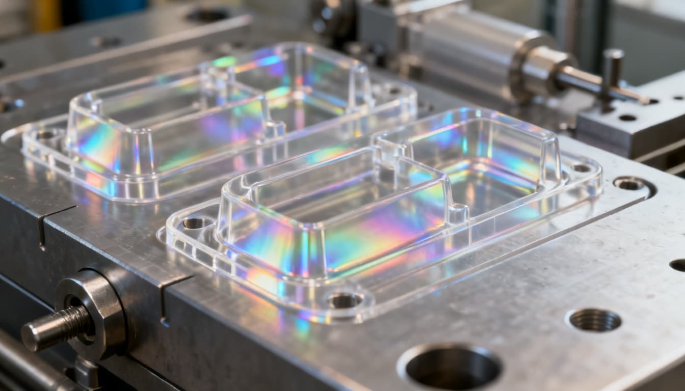
Injection molding inherently introduces molecular orientation as polymer chains align with the flow front. When that orientation freezes before the chains can relax, the material becomes optically anisotropic — its refractive index varies with polarization direction. This photoelastic effect is invisible to the naked eye but easily detected by a polariscope. Recent molding failures in automotive forward-lighting lenses show how subtle this can be: firstmold.com notes that “birefringence can occur due to stress or strain during the molding process,” and that low-birefringence materials are essential to manage molding conditions. Meanwhile, Fictiv reports that for optical components in automotive lighting, “too little packing or holding results in sink marks and poor dimensional accuracy, while too much induces stress birefringence (photoelastic effect), reducing optical clarity by altering the material’s refractive index.” In both cases, the failure mode wasn’t a material defect — it was a process window that prioritized cycle time over molecular relaxation.
For product engineers and buyers, the message is clear: optical injection molding demands a different decision framework than standard plastic parts. You need to understand how filling-stage dynamics lock in orientation, how material selection sets the baseline for stress birefringence, and which DFM rules keep your lens performing from shot one to shot one million. The following sections give you that framework, grounded in published research and real production data.
How Flow-Induced Stress During Mold Filling Determines Residual Birefringence
If you’ve ever assumed that birefringence is primarily a cooling or packing problem, the data will surprise you. A detailed study from the University of Arizona (Sauther et al.) compared numerical predictions with experimental measurements and concluded that “the residual birefringence is mainly generated during the mold-filling stage.” As the melt front advances, polymer molecules stretch and orient along flow lines. The high shear rates near the cavity wall freeze this orientation almost instantly, while the slower-cooling core may relax partially. Packing pressure can modulate the final level of orientation, but it cannot erase what the filling stage has already locked in.
This finding has direct consequences for process setup. If you focus solely on packing pressure and ignore injection speed or melt temperature, you’re fighting the wrong battle. The table below summarizes how key molding parameters influence residual birefringence, drawing on the Arizona study, Fictiv’s process guidelines, and the Photonics Handbook for specifying polymer optics.
| Process Parameter | Influence on Residual Birefringence | Typical Adjustment to Minimize OPD | Notes |
|---|---|---|---|
| Injection Speed (Flow Rate) | Higher speed increases shear rate and molecular orientation, raising birefringence. Too low can cause short shots or hesitation marks. | Moderate speed; profile to slow down near gate freeze-off. Typical linear velocity 50–150 mm/s for optical PMMA. | Filling-stage shear dominates; the Arizona study shows OPD rises sharply with injection rate. |
| Melt Temperature | Higher temperature reduces viscosity, allowing more molecular relaxation before solidification. Excessive heat risks polymer degradation and yellowing. | Set at upper end of supplier’s recommended range: PMMA 240–260°C, PC 290–310°C, COP 270–300°C. | Relaxation time decreases exponentially with temperature; a 10°C increase can cut birefringence by 15–25%. |
| Mold Temperature | Elevated mold temperature slows cooling, giving chains more time to relax. However, cycle time increases and part sticking may occur. | Use the highest practical mold temperature: 80–100°C for PMMA, 100–130°C for PC, 120–140°C for COP. | For thin-walled lenses, mold temperature is critical to avoid frozen-in orientation near the surface. |
| Packing Pressure & Time | Packing compresses the melt and can re-orient molecules, but its effect is secondary to filling. Insufficient packing causes sink and density variations that alter refractive index. | Apply a packing profile that decays gradually; hold until gate freeze. Peak pressure typically 60–80% of injection pressure. | Over-packing induces additional photoelastic stress; monitor cavity pressure to find the knee point. |
| Gate Location & Size | Gate placement determines flow direction and weld line position. A gate that forces the melt to split and recombine creates high-birefringence weld zones. | Use a single edge gate or a film gate along the non-optical edge. Avoid multiple gates that create knit lines in the optical path. | Simulate gate freeze-off to ensure packing can be transmitted to the lens center. |
| Cooling Time & Uniformity | Non-uniform cooling generates thermal stresses that add to flow-induced birefringence. Differential shrinkage across thick and thin sections is a common source. | Design conformal cooling channels; maintain ΔT across the cavity below 5°C. Cooling time should allow part ejection below HDT. | Rapid, uneven cooling can produce birefringence patterns that mimic flow marks. |
Key takeaway: To control birefringence, start by profiling injection speed and raising melt and mold temperatures as high as the material and cycle time allow. Then use packing only to compensate for volumetric shrinkage — not to force orientation into submission. Validate the process window with a polarimeter, measuring optical path difference (OPD) in nm/cm. For many imaging applications, keeping OPD below 20 nm/cm across the clear aperture is a practical target, though LiDAR and interferometric systems often demand <10 nm/cm.
COP vs PMMA vs PC: Choosing a Low-Birefringence Resin for Thermal and Optical Demands
Material selection is the single most powerful lever you can pull to reduce birefringence before the mold is even cut. Each optical-grade resin has a characteristic “native” stress-optical coefficient — a measure of how much birefringence it develops under a given stress. Cyclic olefin polymers (COP/COC) stand out for their exceptionally low stress birefringence and low moisture absorption, making them the first choice for precision visible-spectrum optics that must survive temperature and humidity swings. Polycarbonate (PC) offers high impact strength and a heat deflection temperature (HDT) above 130°C, but its higher stress-optical coefficient and moisture sensitivity demand tighter process control. PMMA (acrylic) remains the workhorse for cost-sensitive applications where surface hardness and UV stability are paramount, though its birefringence performance falls between COP and PC.
The comparison table below draws on data from ATR Mold’s material selection guide, G&H’s polymer optics expertise, FirstMold’s COC analysis, and Laser Focus World’s review of advances in polymer optics. Specialty grades such as Zeonex® and optical liquid silicone rubber (LSR) are included for edge cases where standard resins fall short.
| Material | Transmittance (Visible, 3 mm) | Refractive Index (nd) | Stress Birefringence (Relative) | HDT @ 1.82 MPa (°C) | Moisture Absorption (24 h, %) | Key Trade-offs |
|---|---|---|---|---|---|---|
| PMMA (Acrylic) | 92% | 1.49 | Moderate | 95–105 | 0.3 | Excellent surface hardness and UV stability; higher birefringence than COP; prone to stress cracking with solvents. |
| Polycarbonate (PC) | 88–90% | 1.58 | High | 130–140 | 0.2 | Superior impact and thermal resistance; high native birefringence demands precise process control; yellows under UV without stabilization. |
| COP (e.g., Zeonex®) | 91–92% | 1.53 | Very Low | 120–140 (depending on grade) | <0.01 | Lowest birefringence and moisture absorption; excellent for automotive sensors and medical optics; higher material cost. |
| COC (e.g., TOPAS®) | 90%+ | 1.53 | Low | 130–150 | <0.01 | Similar to COP with slightly higher HDT; good flow for thin walls; limited chemical resistance to non-polar solvents. |
| Optical Silicone (LSR) | 88–94% (depending on formulation) | 1.40–1.54 | Very Low | 200+ (thermoset) | 0.1–0.3 | Extreme thermal stability and flexibility; used for secondary optics and LED encapsulants; requires dedicated LSR tooling and processing. |
Selection guidance: For LiDAR collimators and automotive exterior sensors that see -40°C to +105°C and condensing humidity, COP is the default choice — its near-zero moisture uptake and low birefringence keep focal length and beam quality stable. When the lens must withstand repeated autoclaving or chemical sterilization, COP again outperforms PMMA. PC earns its place in high-temperature interior applications (projector lenses, LED secondary optics) where its toughness and HDT outweigh the birefringence penalty, provided you invest in rigorous process development. PMMA remains the most economical option for indoor visible-light optics, light guides, and display lenses where thermal and moisture extremes are absent. As ATR Mold notes, engineering-grade resins like LCP and PEEK are also emerging for LiDAR and sensing applications, but they require different tooling and process approaches — consult your molder early if you’re considering these.
DFM Rules That Prevent Birefringence and Hold Sub-Micron Surface Replication
Standard DFM for injection molding focuses on wall thickness uniformity, draft angles, and knit-line avoidance. Optical DFM goes much further: it must control molecular orientation, sub-micron surface replication, and cavity-to-cavity consistency. As ATR Mold’s optical DFM guide emphasizes, “standard DFM fails to evaluate the variables that govern optical performance: birefringence from flow-induced molecular orientation, sub-micron surface replication fidelity, focal length shifts from differential shrinkage, and transmittance.” Skipping these steps means you’ll pay for it in yield loss and requalification.
The foundation of optical DFM is mold-flow simulation that goes beyond fill pattern. You need to simulate shear rates, packing pressure distribution, and volumetric shrinkage at every node of the lens. This data allows toolmakers to perform precise mold cavity compensation on the inserts — not generic shrinkage factors from a datasheet, but local, simulation-driven offsets that correct for differential shrinkage across the lens profile. For multi-cavity molds, simulation must verify that each cavity fills at identical shear rates and packing pressures; otherwise, cavity-to-cavity focal length variation will render your production incapable of meeting optical specifications.
Gate location is the single most influential DFM decision for birefringence. A gate placed at the lens periphery and oriented to create a uniform, radial flow front minimizes orientation gradients. Avoid center gates that force the melt to flow outward in all directions, creating a high-birefringence star pattern. If a center gate is unavoidable due to part geometry, use a generous cold slug well and a tapered sprue to manage orientation, and simulate the resulting OPD map to confirm it stays within spec.
Surface finish requirements for optical molds are an order of magnitude tighter than for cosmetic parts. The table below summarizes the mold insert specifications needed to achieve birefringence-controlled, optically smooth surfaces, based on Laser Focus World’s manufacturing data and industry practice.
| Specification | Requirement | Why It Matters for Birefringence & Clarity |
|---|---|---|
| Insert Steel | Stavax ESR, NAK80, or equivalent stainless tool steel | High polishability and corrosion resistance; uniform microstructure minimizes thermal stress. |
| Plating | Electroless nickel, 50–100 µm thick | Nickel provides the ductility needed for single-point diamond turning (SPDT) and protects against corrosive outgassing from some polymers. |
| Surface Roughness (Ra) | ≤20 Å (2 nm) after SPDT and post-polish | Sub-nanometer roughness prevents scatter and preserves wavefront quality; any micro-groove from machining can act as a stress concentrator. |
| Machining Method | Single-point diamond turning (SPDT) on nickel-plated inserts | SPDT produces the continuous, rotationally symmetric surface required for refractive optics; tool marks must be below the wavelength of light. |
| Form Accuracy (Peak-to-Valley) | ≤0.5 µm over the clear aperture | Deviation from the designed aspheric or spherical profile directly introduces wavefront error and can amplify local birefringence through thickness variation. |
| Lead Time | 8–10 weeks typical for a single-cavity optical mold | Includes insert machining, SPDT, metrology validation, and mold assembly; rush orders risk compromising surface quality. |
| Cooling Layout | Conformal cooling channels, often via additive manufacturing | Uniform cooling prevents thermal gradients that induce stress birefringence and part warpage; conformal channels follow the optical contour. |
Process window validation: Once the mold is built, run a design of experiments (DOE) varying injection speed, packing pressure, and mold temperature. Measure birefringence on molded samples with a polarimeter and map OPD across the clear aperture. Lock the process window that yields the lowest and most stable OPD, and use cavity pressure sensors to monitor every shot. If cavity pressure curves drift, you know birefringence is shifting before a single part is measured optically. This is the only way to guarantee that your production lenses match the qualification samples.
Optical Injection Molding: Questions Engineers Should Ask Before Tooling Begins
Senior engineers and procurement leads face nuanced decisions when optical performance is at stake. The following answers address the most common questions we field from teams transitioning from mechanical to optical injection molding.
Q: How much birefringence is acceptable for a collimating lens in a LiDAR system?
A: It depends on the optical path length and detector sensitivity, but typically a maximum optical path difference of 10–20 nm/cm is targeted. For LiDAR, even low levels can distort beam shape and reduce ranging accuracy. Specifying <10 nm/cm for critical surfaces is common, verified by polariscope inspection after molding. The Arizona study (Sauther et al.) shows that achieving this requires careful control of filling-stage parameters, not just packing.
Q: What mold steel and surface finish do I need to achieve 20 Å roughness on optical inserts?
A: Nickel-plated steel (e.g., Stavax or NAK80) single-point diamond turned (SPDT) is the industry standard. The nickel layer provides the ductility needed for diamond machining, and post-polishing can achieve <20 Å Ra. Tooling lead times are typically 8–10 weeks, as reported by Laser Focus World. Rushing this process risks tool marks that act as stress concentrators and increase local birefringence.
Q: Can I use multi-cavity molds without introducing cavity-to-cavity focal length variation?
A: Yes, but only with rigorous mold-flow simulation to balance fill shear rates and packing pressure across all cavities. Without it, differential shrinkage will cause focal length shifts. In-situ cavity pressure sensors and process window validation are essential for production consistency. ATR Mold’s DFM guide emphasizes that simulation must verify identical shear rates and packing pressures in every cavity to prevent this variation.
Q: What drying and processing conditions prevent moisture-induced birefringence in polycarbonate?
A: PC requires drying to <0.02% moisture content (typically 120°C for 4 hours with a desiccant dryer) to avoid splay and hydrolytic degradation that amplifies stress birefringence. Processing with a properly sized dryer and short residence time at the melt temperature minimizes molecular weight loss and optical defects. Even small amounts of moisture can increase the stress-optical coefficient, making the material more sensitive to flow-induced orientation.
Q: How do I validate that my molder’s process window won’t introduce stress birefringence over production volumes?
A: Conduct a design of experiments (DOE) varying injection speed, packing pressure, and mold temperature, then measure birefringence on molded samples with a polarimeter. Lock the process window that yields the lowest and most stable optical path difference, and monitor with cavity pressure curves during production to detect drift. If cavity pressure deviates beyond the validated corridor, birefringence is likely shifting — stop and investigate before shipping non-conforming lenses.
Q: When should I consider COP over PMMA for thermal stability without sacrificing clarity?
A: COP offers lower birefringence and moisture absorption than PMMA, with higher HDT than PC in some grades. Choose COP when the lens will see elevated temperatures (>100°C) and humidity swings that would distort PMMA’s refractive index, such as in automotive exterior sensors or medical devices requiring repeated autoclaving. FirstMold notes that “many precision optical systems prefer COC because of its low dispersion and birefringence, which lead to less optical distortion.” COP delivers that same advantage with even better moisture resistance.
Optical injection molding demands a systems-level approach: material, mold design, process parameters, and validation must all align around the goal of minimizing stress birefringence while maintaining sub-micron form accuracy. By applying the selection criteria and DFM rules outlined here, you can avoid the costly trap of high-transmission lenses that fail in the field. For a deeper discussion of your specific optical project, get a quote from our engineering team — we’ll help you navigate material choices, mold design, and process validation to meet your birefringence and clarity targets.
References & Further Reading
- Optical Injection Molding: Precision Optics Manufacturing – FirstMold
- Injection Molding Process Parameters: How to Adjust for Quality, Efficiency, and Defect Prevention – Fictiv
- Study of process parameters on optical qualities for injection molded lenses – University of Arizona (Sauther et al.)
- DFM for Optical Lens Injection Molding: Skip It, Pay Twice – ATR Mold
- PMMA vs PC vs COP: Optical Lens Material Selection Guide 2026 – ATR Mold
- Materials for Polymer Optics – G&H
- POLYMER OPTICS: Progress in plastic optics follows advances in materials and manufacturing – Laser Focus World
- Plastic Optics: Specifying Injection-Molded Polymer Optics – Photonics Handbook