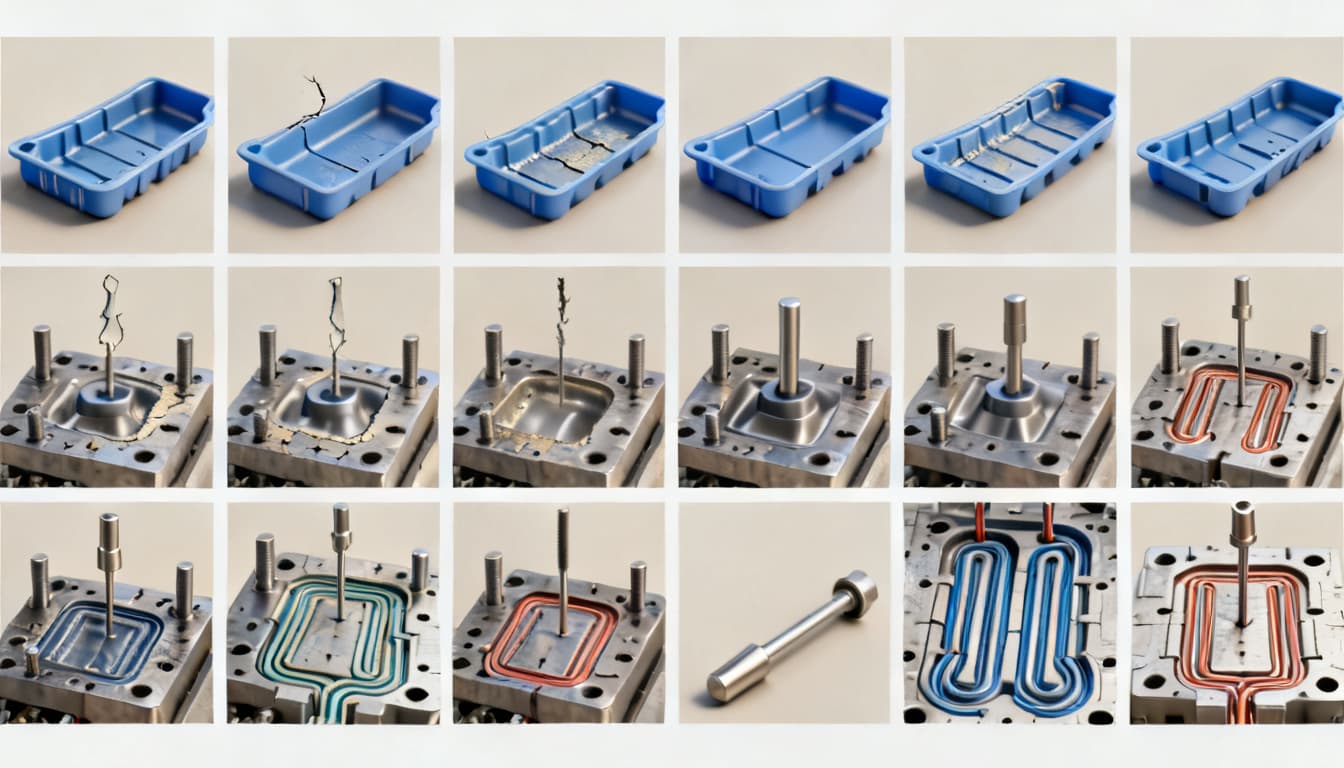
The Product Engineer’s Quick-Reference Matrix: 12 Injection Molding Defects and Their Proven Remedies
When a batch of molded parts comes out of the press with flash, short shots, or warpage, the immediate reaction is to calculate the scrap cost. But that number—the raw material and machine time lost—is only the tip of the iceberg. For product engineers and injection molding buyers, defects ripple th
Why Injection Molding Defects Are Costing You More Than Scrap Rates
When a batch of molded parts comes out of the press with flash, short shots, or warpage, the immediate reaction is to calculate the scrap cost. But that number—the raw material and machine time lost—is only the tip of the iceberg. For product engineers and injection molding buyers, defects ripple through the supply chain in ways that erode margins, delay launches, and damage customer relationships long after the rejected parts are reground.
Unplanned downtime is the silent profit killer. A single recurring defect can force a production line into diagnostic mode for hours, sometimes days. According to a recent production manager’s guide on injection molding machine diagnostics, the difference between a well-maintained cell and one that reacts to defects is measured in OEE (Overall Equipment Effectiveness) drops of 15–25% and MTBF (Mean Time Between Failures) that can halve within a quarter Tederic downtime guide. Every minute a press isn’t making good parts, you’re paying for overhead, labor, and missed shipment windows.
Quality escapes are even more expensive. When a defect isn’t caught at the press and reaches assembly or, worse, the end customer, the cost multiplies. Ronningen Research’s defect guide highlights that common quality control issues—like inconsistent dimensions or surface blemishes—often go undetected until secondary operations, where rework or field returns can cost 10× the original part price Ronningen defect guide. For a buyer managing multiple tools across different suppliers, one undiagnosed defect pattern can trigger a cascade of line-down situations.
The good news is that most defects are preventable with a structured troubleshooting approach. A case study from Tederic documented an 82% reduction in scrap after a processor implemented systematic defect identification and parameter optimization, moving from reactive firefighting to data-driven process control Tederic defects & solutions. That kind of improvement doesn’t require a new press or exotic materials—it demands that engineers and buyers speak the same defect language and have a quick-reference framework to act fast.
This article gives you that framework. We’ve distilled the 12 most frequent injection molding defects into a matrix you can use on the shop floor or during a supplier audit. You’ll learn to recognize each defect’s visual signature, trace it to the most likely root cause category, and apply a proven first-response remedy. Along the way, we’ll compare machine, mold, and material remediation paths, and show you how to build a prevention system that pays for itself in months, not years. For a broader overview of defect types and prevention, RapidDirect’s complete guide reinforces that early defect recognition is the cornerstone of efficient manufacturing RapidDirect guide.
The 12 Defects Every Product Engineer Should Recognize at a Glance
Injection molding defects rarely announce themselves with a single root cause. A short shot might look like a material starvation issue, but it could equally stem from a cold mold, a blocked vent, or a worn check ring. That’s why the first step isn’t to twist a knob—it’s to identify the defect pattern and map it to the most probable category: machine, mold, material, or process. The matrix below gives you that starting point, built from real troubleshooting experience and mold design fundamentals.
Mold geometry and cooling layout are frequent hidden drivers. As detailed in Upmold’s mold specification guidelines, uneven cooling channels or inadequate draft angles can produce warpage and sink marks that no amount of process tweaking will fully cure Upmold. Similarly, HASCO’s design specifications emphasize that gate size and location directly influence flow patterns and the likelihood of jetting or weld lines HASCO. Use this matrix to narrow down where to look first, then dive deeper with the comparison and guidance sections that follow.
| Defect | Visual Signature | Primary Root Cause Category | Typical First-Response Remedy |
|---|---|---|---|
| Short Shot | Incomplete part; missing sections, especially at thin walls or far from gate | Process / Machine | Increase shot size and injection speed; verify cushion and check ring |
| Flash | Thin film of plastic extending from parting line or ejector pin | Machine / Mold | Check clamp force and mold closure; clean parting line; reduce injection pressure |
| Sink Marks | Localized surface depressions, often above thick ribs or bosses | Mold / Process | Reduce melt temperature; increase packing pressure and time; optimize wall thickness transitions |
| Voids | Internal bubbles; part feels light or shows shadow when backlit | Process / Material | Increase packing pressure; dry material thoroughly; lower melt temperature to prevent gas entrapment |
| Warpage | Part distortion; bends or twists out of intended shape | Mold / Process | Balance cooling circuits; reduce differential shrinkage by adjusting mold and melt temperatures |
| Weld Lines | Visible line or notch where two flow fronts meet, often around holes | Mold / Process | Increase melt and mold temperature; relocate gate to alter flow front meeting point |
| Jetting | Snake-like, wavy surface pattern near gate | Mold / Process | Enlarge gate or use a tab gate; reduce injection speed; increase melt temperature |
| Burn Marks | Brown or black discolorations, often at end of fill or near vents | Process / Mold | Reduce injection speed; improve venting; lower melt temperature |
| Flow Marks | Wavy, ring-shaped lines on part surface near gate | Process / Material | Increase injection speed and melt temperature; ensure material is dry and nozzle is not partially blocked |
| Delamination | Flaky, peeling surface layers; part can be easily separated | Material / Process | Dry material to specification; check for contamination; reduce regrind percentage |
| Brittleness | Parts crack or break under normal handling or assembly | Material / Process | Reduce melt temperature and residence time; verify material drying; check for degradation |
| Discoloration | Localized or overall color change from masterbatch or natural resin | Material / Process | Purge barrel thoroughly; reduce melt temperature; check colorant carrier compatibility |
Key takeaway: The matrix is a triage tool, not a final diagnosis. A short shot that persists after increasing shot size may point to a worn screw or a gate freeze-off issue—both mold and machine factors. The next section helps you decide whether to chase a machine setting, rework the mold, or focus on material prep.
Machine Settings vs. Mold Design vs. Material Prep: Which Remedy Path Fits Your Defect?
Once you’ve identified a defect, the temptation is to start adjusting barrel temperatures or injection velocity. But not all defects respond to process tweaks. Some are baked into the mold steel, and others originate at the resin dryer. Choosing the wrong remedy path wastes production time and can mask the true root cause, leading to intermittent failures that are even harder to diagnose later.
Industry resources consistently group corrective actions into three buckets: machine/process parameter tuning, mold modification, and material handling. Sofeast’s pilot-run FAQs stress that many defects first appear during qualification runs, where process windows are still being established, and that a structured approach to isolating variables prevents endless trial-and-error Sofeast pilot-run FAQs. M. Holland’s troubleshooting guide, built on 30 years of field experience, echoes that addressing defects promptly requires knowing which lever to pull first—and when to call for tooling changes M. Holland's 10-defect troubleshooting.
Mold design guidelines from Protolabs highlight that features like uniform wall thickness, generous radii, and proper draft can eliminate many defects before the mold is even cut Protolabs design guidelines. Meanwhile, machine specification guides from Daoben remind buyers that clamp tonnage, shot size, and injection speed capabilities must match the mold and material requirements to avoid flash, short shots, and inconsistent filling Daoben machine spec evaluation. The comparison table below helps you decide which path to pursue based on defect type, timeline, and cost.
| Remedy Path | Typical Defects Addressed | Implementation Time | Cost & Risk | When to Choose |
|---|---|---|---|---|
| Process Parameter Tuning | Short shots, flash, sink marks, burn marks, flow marks, weld lines | Minutes to hours | Low cost; risk of creating new defects if changes are not documented | Defect appears suddenly on a previously stable tool; quick adjustments can restore process window |
| Mold Modification | Warpage, jetting, persistent weld lines, sink marks due to thick sections | Days to weeks (tooling rework) | Moderate to high; requires skilled toolmaker; risk of irreversible changes | Defect is inherent to part/mold design; process window cannot compensate; multiple batches show same pattern |
| Material Handling & Prep | Delamination, brittleness, discoloration, voids from moisture | Hours (drying) to days (material lot change) | Low to moderate; cost of dryer maintenance or new resin lot | Defect correlates with material lot change, high humidity, or regrind usage; drying logs show deviation |
In practice, many defects require a combination. For example, flash on a tool that ran well for years might first be addressed by checking clamp force (machine), but if the parting line is worn, mold rework is inevitable. The key is to avoid the trap of endlessly chasing process parameters when the mold or material is the true culprit. Use the matrix to form a hypothesis, then test the fastest, least invasive path first. If a 10-minute injection speed adjustment eliminates burn marks, you’ve saved a tooling teardown. If not, you’ve gathered data that points toward venting or material degradation.
From Quick Fix to Systemic Prevention: Actionable Remedies for Your Production Line
A quick-reference matrix is only as good as the system that uses it. The real payoff comes when you move from reactive troubleshooting to a prevention playbook that catches defects before they become scrap events. This shift requires three things: a method to prioritize defects by business impact, in-process checks that provide early warning, and a quality management framework that ties it all together.
Start by ranking defects by frequency and cost. A short shot that stops production entirely may cost more per hour than occasional sink marks that are cosmetically acceptable. Matrix Tool’s quality management system emphasizes defect prevention and waste reduction through statistical process control and proactive mold maintenance, not just final inspection Matrix Tool quality. Adopting a similar mindset means you’ll instrument the process to detect deviations in real time, rather than sorting parts after the run.
The Injection Molding Handbook (3rd Ed.) provides the engineering backbone for this approach, detailing how to calculate mold strength, optimize packing profiles, and set up robust process windows that account for normal variation Injection Molding Handbook. The table below lists the key parameters you should monitor and how they tie to the 12 defects. Integrating these into a daily checklist or a real-time monitoring system turns the matrix into a living document.
| Parameter | Typical Monitoring Range | Defects Influenced | Monitoring Method |
|---|---|---|---|
| Melt Temperature | ±5°C of resin supplier recommendation | Short shots, burn marks, brittleness, discoloration | In-barrel thermocouples; handheld pyrometer for nozzle check |
| Mold Temperature | ±3°C across cavity surfaces | Warpage, sink marks, weld lines, flow marks | Thermal imaging camera or mold surface probes |
| Injection Pressure (peak) | Within 10% of established process window | Flash, short shots, jetting | Machine pressure transducer; cavity pressure sensors |
| Injection Speed | Profile stages within ±5% of setpoint | Burn marks, flow marks, jetting | Machine control feedback; high-speed data acquisition |
| Cushion / Shot Size | Cushion 3–6 mm; shot size repeatable within 1% | Short shots, flash | Machine position transducer; weigh shots periodically |
| Material Moisture Content | <0.02% for hygroscopic resins (e.g., nylon, PC) | Voids, delamination, brittleness | Moisture analyzer; dryer dew point monitor |
| Clamp Force | Within 5% of required tonnage; verified periodically | Flash, mold damage | Strain gauges on tie bars; machine tonnage readout |
Tip: For buyers auditing a supplier, ask to see their process monitoring logs and how they correlate parameter drift with defect occurrence. A molder that can show you a control chart of cushion values and explain how they prevent short shots is far more valuable than one that simply sorts parts. If you’re justifying investment in real-time monitoring to your management, frame it around OEE and MTBF benchmarks. The Tederic downtime guide referenced earlier provides calculators that show how a 5% improvement in OEE can offset monitoring system costs within months. And the 82% scrap reduction case study is a concrete ROI example you can cite: fewer defects mean more saleable parts per shift, directly boosting throughput without adding presses.
Build a prevention playbook that includes a defect response flowchart for each tool. When an operator sees a flash, the flowchart directs them to check clamp tonnage and parting line cleanliness before calling a technician. This standardizes the first-response remedies from the matrix and captures data that feeds continuous improvement. Over time, you’ll see patterns—maybe a particular material lot always needs a slightly higher melt temperature—and you can adjust the process window proactively.
Your Toughest Defect Questions, Answered by Process Engineers
After using the matrix and comparing remedy paths, product engineers and procurement leads often have nuanced questions that go beyond the basic definitions. Here are the answers that will help you make confident decisions on the floor or during a supplier review.
Q: How do I quickly tell the difference between a sink mark and a void without cutting the part?
Sink marks are surface depressions you can feel with a fingernail; they typically form above thick ribs or bosses where the outer skin solidifies before the core shrinks. Voids are internal bubbles—the surface remains smooth, but the part may feel lighter than expected or show a dark shadow when held up to a light. A quick density check (weighing the part and comparing to the theoretical weight) can confirm a void. If you’re still unsure, a low-pressure sectioning with a saw often reveals the internal cavity without destroying the entire part. Remember, sink marks usually respond to increased packing pressure and time, while voids often require better drying or lower melt temperature to prevent gas entrapment.
Q: When should I suspect mold temperature versus melt temperature as the main driver of warpage?
If warpage is consistent and directional—say, every part bows toward the fixed half of the mold—uneven mold cooling is the prime suspect. Use a thermal imaging camera to check for temperature differences across cavity surfaces; a variation of more than 5°C can induce differential shrinkage. If warpage appears randomly or only after a material or color change, melt temperature and residual stress from filling are more likely. In that case, look at your injection speed profile and packing pressure decay. Adjusting mold temperature is a slower fix (it takes time for the mold to stabilize), so rule out process-related causes first.
Q: What's the first parameter I should adjust when flash appears on a previously stable tool?
Start with clamp force and injection pressure. Flash often signals that the clamp tonnage has dropped—perhaps due to worn toggle linkages or a hydraulic leak—or that injection pressure has spiked because of a partially blocked nozzle or hot runner. Verify the mold is fully closed and the parting line is clean; a small piece of debris can hold the mold open just enough to flash. If clamp force and pressure are normal, check the mold for wear at the parting line or around ejector pins. Don’t immediately lower melt temperature; that can cause other defects like short shots.
Q: Can a single defect like short shots have multiple root causes, and how do I prioritize them?
Absolutely. Short shots can result from insufficient shot size, low injection speed, air traps, material viscosity shifts, or a worn check ring. Prioritize by checking the simplest and fastest: verify the cushion and shot size first—if the screw isn’t reaching its setpoint, you’ve found the problem. Next, look for venting issues; a blocked vent can prevent the cavity from filling completely. Only then adjust melt temperature or consider a material change. This logical sequence prevents you from masking a mechanical issue with a process band-aid that will fail later.
Q: How do I justify investing in real-time process monitoring to management?
Frame the conversation around OEE and MTBF benchmarks from machine diagnostics guides. Real-time monitoring catches pressure or temperature deviations before they produce scrap, preventing events that cost 5–10× the annual monitoring investment in material, machine time, and rework. Cite the 82% scrap reduction case study as a tangible ROI example: if your current scrap rate is 5% and monitoring cuts it to 1%, the savings on a single press can exceed $30,000 per year. Add the avoided costs of missed shipments and customer returns, and the payback period is often under six months. Monitoring also provides the data you need to hold suppliers accountable and to optimize cycle times safely.
References & Further Reading
- Injection Molding Machine Diagnostics & Service – Production Manager's Guide – Tederic downtime cost calculator, OEE/MTBF benchmarks.
- Injection Molding Quality Control: Ronningen's Defect Guide – Common QC issues and how to resolve them.
- Injection Molding Defects – Identification, Causes and Solutions – Tederic case study with 82% scrap reduction.
- Injection Molding Defects: Causes, Types & Prevention – RapidDirect complete defect overview.
- Plastic Injection Molding Questions: 17 Top FAQs – Sofeast pilot-run and quality insights.
- Engineering Insights: How to Solve 10 Common Injection Molding Defects – M. Holland troubleshooting guide.
- Injection Molding Design Guide – Protolabs Network design rules for defect-free parts.
- Injection Mold Machine Specs: 7 Critical Factors to Review – Daoben machine evaluation guide.
- Injection Mold Specifications & Plastic Mold Design Guideline – Upmold mold design standards.
- Plastic Injection Molding Quality Management System – Matrix Tool defect prevention approach.
- Specifications for Injection Moulds – HASCO design specifications (PDF).
- Injection Molding Handbook (3rd Ed.) – Comprehensive reference for process optimization and mold strength.
Whether you’re troubleshooting a single tool or building a plant-wide defect prevention system, the matrix and remedy paths in this article give you a head start. For help with mold design reviews, process optimization, or supplier quality audits, get in touch with our team to discuss your next project.