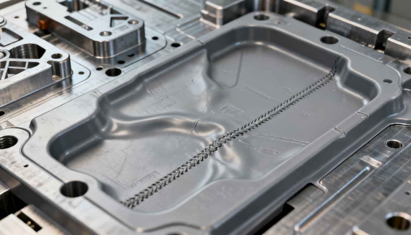
Troubleshooting Plastic Part Design: Fixing Warpage, Sink Marks, and Weak Knit Lines
Even after decades of molding experience, three defects—warpage, sink marks, and weak knit lines—continue to cause tooling rework, delayed shipments, and unacceptable scrap rates. A recent roundup of injection molding defects by Fictiv places sink marks, warping, and flow lines (which often manifest
Troubleshooting Plastic Part Design: Fixing Warpage, Sink Marks, and Weak Knit Lines
Why Warpage, Sink Marks, and Knit Lines Still Derail Production Timelines
Even after decades of molding experience, three defects—warpage, sink marks, and weak knit lines—continue to cause tooling rework, delayed shipments, and unacceptable scrap rates. A recent roundup of injection molding defects by Fictiv places sink marks, warping, and flow lines (which often manifest as visible knit lines) among the top ten production killers. Similarly, IMS-tex emphasizes that preventive solutions in part design—coring out thick sections, reinforcing with ribs, and maintaining consistent wall thickness—are far more effective than chasing process parameters after the mold is cut.
Supply chain teams feel the pain directly. A single design oversight that leads to excessive warpage can push a pilot run back by weeks while the mold is modified. Elastron notes that warpage is driven by differential cooling, a root cause that often originates in the CAD model, not the molding machine. Meanwhile, 3ERP highlights that advanced simulation software can visualize flow, cooling, and warping before steel is cut, yet many programs still skip this step to save upfront cost—only to pay for it later in rework and missed deadlines. The data is clear: early design intervention, grounded in the physics of plastic shrinkage, prevents the majority of field failures. In the sections that follow, we’ll translate that physics into actionable design rules you can apply today.
The Physics of Plastic Shrinkage: Why Uniform Walls Are Non-Negotiable
Sink marks, warpage, and weak knit lines all trace back to a single phenomenon: differential cooling and shrinkage. When molten plastic enters a mold, it begins to cool from the outside in. Thick sections retain heat longer and shrink more as they solidify, pulling the surface inward to create a sink mark. If cooling rates vary across the part, internal stresses build up and release as warpage. And when two flow fronts meet at a knit line, the strength of that weld depends on how well the polymer chains entangle—something that is compromised by premature cooling or contamination at the flow front.
Aprios identifies non-uniform wall thickness as the single most significant cause of sink marks. Ensinger Precision Components reinforces that uneven cooling rates lead to distortion, while Polymer Molding explains that high packing pressures can reduce sink depth but won’t fix a design with inherently thick sections. The design rule that ties all this together comes from Rex Plastics: rib thickness should not exceed 60% of the adjoining wall thickness to prevent sink. Jaycon illustrates the difference between a solid, warp-prone boss and a properly shelled design that maintains uniform walls.
The table below summarizes the key wall thickness parameters that govern sink and warp behavior. Use it as a quick-reference during design reviews.
| Parameter | Recommended Value / Range | Notes & Failure Boundary |
|---|---|---|
| Nominal wall thickness | 1.5–4.0 mm (typical for engineering thermoplastics) | Thinner walls reduce cycle time but may limit fill; thicker walls increase sink risk. |
| Wall thickness variation | ±10–15% maximum across the part | Sudden changes (e.g., 4 mm to 1.5 mm) almost guarantee differential cooling and warpage. |
| Rib-to-wall ratio | ≤ 60% of nominal wall | Ribs thicker than 60% create a localized mass of material that cools slowly, causing sink on the opposite surface. |
| Boss OD-to-wall ratio | ≤ 2× nominal wall for outer diameter | Thick bosses should be cored out from the back to maintain uniform wall thickness. |
| Corner radii (internal) | ≥ 0.5× wall thickness | Sharp internal corners concentrate stress and disrupt flow, weakening knit lines. |
| Transition zones | Gradual taper over at least 3× thickness difference | Abrupt steps cause flow hesitation and uneven cooling. |
| Gate location relative to knit line | Position gate so knit line forms in low-stress area | Knit lines in high-load regions can reduce part strength by up to 50% in glass-filled grades. |
| Cooling circuit balance | ΔT across mold halves < 5°C | Uneven mold temperatures drive differential shrinkage and warpage. |
Knit line formation deserves special attention. When two melt fronts converge, the polymer molecules at the interface may not fully entangle if the fronts have cooled too much. The result is a localized weakness. Unfilled amorphous resins like ABS or polycarbonate can retain 80–90% of their original tensile strength at a knit line, but glass-filled crystalline materials such as nylon 66 may lose half their strength. That’s why you must treat knit lines as structural features, not cosmetic blemishes, whenever they appear in load-bearing areas.
Rib Reinforcement vs. Coring Out: Choosing the Right Strategy to Eliminate Sink Marks
When a design calls for a thick boss, a deep rib, or a mounting flange that can’t be thinned without sacrificing function, you face a classic design fork: add ribs for stiffness or core out material to maintain uniform walls. Both approaches can eliminate sink marks, but they affect cycle time, tooling cost, and part strength differently. The table below compares the two strategies using published guidelines from Rex Plastics, Ensinger, Polymer Molding, and Aprios, along with simulation insights from 3ERP.
| Comparison Metric | Rib Reinforcement (Thin Ribs, ≤60% Wall) | Coring Out (Hollow Bosses, Uniform Walls) | Selection Criteria & Failure Boundary |
|---|---|---|---|
| Sink mark risk | Low if rib thickness rule is followed; sink appears on opposite surface if ribs exceed 60%. | Very low—uniform wall thickness eliminates differential cooling. | Choose coring when cosmetic surfaces are critical on both sides. |
| Stiffness / strength | High—ribs increase section modulus without adding mass. | Moderate—hollow sections may need additional gussets for stiffness. | Use ribs when stiffness-to-weight ratio is paramount; core out when absolute sink elimination is required. |
| Cycle time | Similar to nominal wall; thin ribs cool quickly. | Often shorter because there is less material to cool. | Coring can reduce cycle time by 10–20% in thick sections. |
| Tooling complexity | Simple—ribs are machined into the core or cavity. | More complex—requires side actions or collapsible cores for deep undercuts. | If the boss is deep and requires a side action, coring may increase tool cost significantly. |
| Material savings | Minimal—ribs add a small amount of material. | Significant—removing material reduces shot weight. | For high-volume programs, material savings from coring can offset tooling investment. |
| Design flexibility | Ribs can be added late in the design cycle with minimal impact on mating components. | Coring changes the part’s internal geometry and may affect assembly interfaces. | Rib reinforcement is often easier to implement as a design fix without altering external dimensions. |
In practice, many successful designs combine both strategies. For example, a mounting boss can be cored out from the back to maintain a uniform wall, then reinforced with four thin gusset ribs that tie the boss to the main wall. This hybrid approach delivers stiffness, eliminates sink, and keeps cycle time in check. 3ERP’s simulation capabilities can validate such designs virtually, showing you the predicted sink depth and warpage displacement before you commit to tooling.
Design Fixes That Work: From Gate Location to Cooling Layout
When a part comes back from the molder with warpage, sink marks, or cracked knit lines, the most effective fixes are almost always geometric, not parametric. Below is a DFM checklist that maps each defect to a specific design action, backed by real-world troubleshooting guides from IDI Composites, Jaycon, and the defect roundups cited earlier.
| Defect | Design Fix | Verification Method |
|---|---|---|
| Sink marks on cosmetic surface opposite a rib or boss | Reduce rib thickness to ≤60% of wall; core out thick bosses; add a textured surface to hide minor sink. | Mold flow simulation; physical cross-sectioning of prototype shots. |
| Warpage (global distortion) | Balance wall thickness; add stiffening ribs in the direction of warp; ensure uniform cooling by repositioning cooling channels or adding baffles. | Warpage simulation (e.g., Moldflow); measure flatness on a surface plate with feeler gauges. |
| Weak knit line in a structural area | Move gate to shift knit line to a low-stress zone; add a flow leader to increase melt temperature at the knit; increase wall thickness locally to promote entanglement. | Tensile test of a specimen cut across the knit line; compare with bulk material strength. |
| Sink on the edge of a flanged part | Add a radius at the flange-to-wall intersection; reduce flange thickness to match the wall; use a thinner flange with gussets. | Visual inspection under controlled lighting; IDI Composites troubleshooting guide notes this as a common failure. |
| Jetting or flow lines that create weak knit lines | Reposition gate to impinge flow against a cavity wall; use a fan gate or tab gate to slow the melt front. | Short-shot series to observe fill pattern; simulation of melt front velocity. |
| Warpage due to asymmetric cooling | Design cooling circuits with equal length and spacing on both mold halves; use conformal cooling for complex geometries. | Thermal imaging of mold surface; simulation of mold temperature distribution. |
Tip: For sink marks, a quick physical test is to add a rib or core out a section on a 3D-printed mold insert and check the surface. This low-cost validation can save a full steel modification. Fictiv’s sink mark troubleshooting guide reinforces that packing pressure alone cannot compensate for a design with thick sections—over-packing risks flash and residual stress. The root fix is always geometric.
When dealing with knit lines, remember that gate location is your most powerful lever. A single gate change can move a knit line from a high-stress boss to a non-critical cosmetic area. If you can’t avoid a knit line in a load path, consider switching to an unfilled grade of the same base resin to improve weld line strength, or use a hot-tip gate to keep the melt front hotter at the convergence point.
Troubleshooting FAQ: Answers for Senior Engineers and Sourcing Teams
Q: How can I tell if a knit line is cosmetic or a structural risk?
A: Check the expected stress at the knit line location and the material’s weld line strength retention. Glass-filled resins can lose up to 50% of their tensile strength at a knit line; unfilled grades may retain 80–90%. If the line falls in a high-load area, treat it as a structural risk. Relocate the gate, add a flow leader, or consider a material change. A simple FEA with a reduced material property at the knit line can quantify the safety factor.
Q: Can I eliminate sink marks entirely by increasing packing pressure?
A: Packing pressure can reduce sink depth but won’t fix a design with thick sections. Over-packing risks flash, molded-in stress, and dimensional instability. The root fix is to maintain uniform wall thickness and follow the rib-to-wall ratio guideline (≤60%). If sink persists, core out the thick area or add a textured surface to mask minor depressions.
Q: What wall thickness variation is acceptable before warpage becomes inevitable?
A: Aim for a maximum variation of ±10–15% across the part. Sudden transitions from thick to thin (e.g., 4 mm to 1.5 mm) almost guarantee differential cooling and warpage. Use gradual tapers and coring to even out mass. If a thick section is unavoidable, add stiffening ribs to resist distortion and balance cooling circuits to minimize temperature gradients.
Q: When should I invest in mold flow simulation versus relying on supplier DFM feedback?
A: For complex geometries, tight tolerances, or high-volume programs, simulation catches warpage and sink marks before tooling is cut. The cost of one tooling rework often exceeds a simulation study. For simpler parts with generous tolerances, a thorough DFM review from an experienced molder may suffice. Many molders now include basic simulation as part of their DFM package—ask for it.
Q: How do material choices (glass-filled vs. unfilled) affect warpage and knit line strength?
A: Glass-filled materials shrink less and can reduce warpage, but they create weaker knit lines and increase tool wear. Unfilled grades flow better and produce stronger knit lines but may warp more due to higher shrinkage. Match material to the part’s functional requirements. If stiffness and dimensional stability are critical, a glass-filled grade with optimized gate locations can work; if impact strength or weld line integrity is paramount, consider an unfilled or impact-modified grade.
Q: What is the fastest way to validate a design fix without cutting new steel?
A: Use rapid tooling (aluminum molds) for prototype shots, or apply mold flow simulation to verify the fix. For sink marks, a quick physical test is to add a rib or core out a section on a 3D-printed mold insert and check the surface. Aluminum tools can be modified quickly and are cost-effective for low-volume validation runs. If the fix works in aluminum, you can confidently transfer it to production steel.
Addressing warpage, sink marks, and weak knit lines early in the design phase is the most cost-effective way to keep your injection molding program on schedule. By applying the wall thickness rules, rib-to-wall ratios, and gate placement strategies outlined here, you can eliminate the majority of these defects before the first shot is fired. When in doubt, a mold flow simulation or a rapid prototype tool will give you the confidence to move forward without risking expensive steel rework.
Ready to review your part design for manufacturability? Get a quote from our engineering team and let’s eliminate warpage, sink marks, and weak knit lines before they reach production.
References & Further Reading
- The 10 Most Common Injection Molding Defects and How to Fix Them – Fictiv
- The Most Common Injection Molding Defects: Causes & Solutions – IMS-tex
- 11 Injection Molding Defects and Troubleshooting – Elastron
- 22 Injection Molding Defects and Mistakes: Causes & Solutions – 3ERP
- Fundamentals of Plastic Part Design Part 3 – Sink and Warp – Rex Plastics
- 6 Common Mistakes in Plastic Part Design and How to Avoid Them – Ensinger Precision Components
- Plastic Part Design Basics: Preventing Sink and Warp – Polymer Molding
- Sink Marks in Injection Molding: Causes and Fixes – Aprios
- Troubleshooting Molding Problems – IDI Composites
- Injection Molding Sink Marks | Troubleshooting – Fictiv
- Engineering Guidelines for Designing Plastic Parts – Jaycon