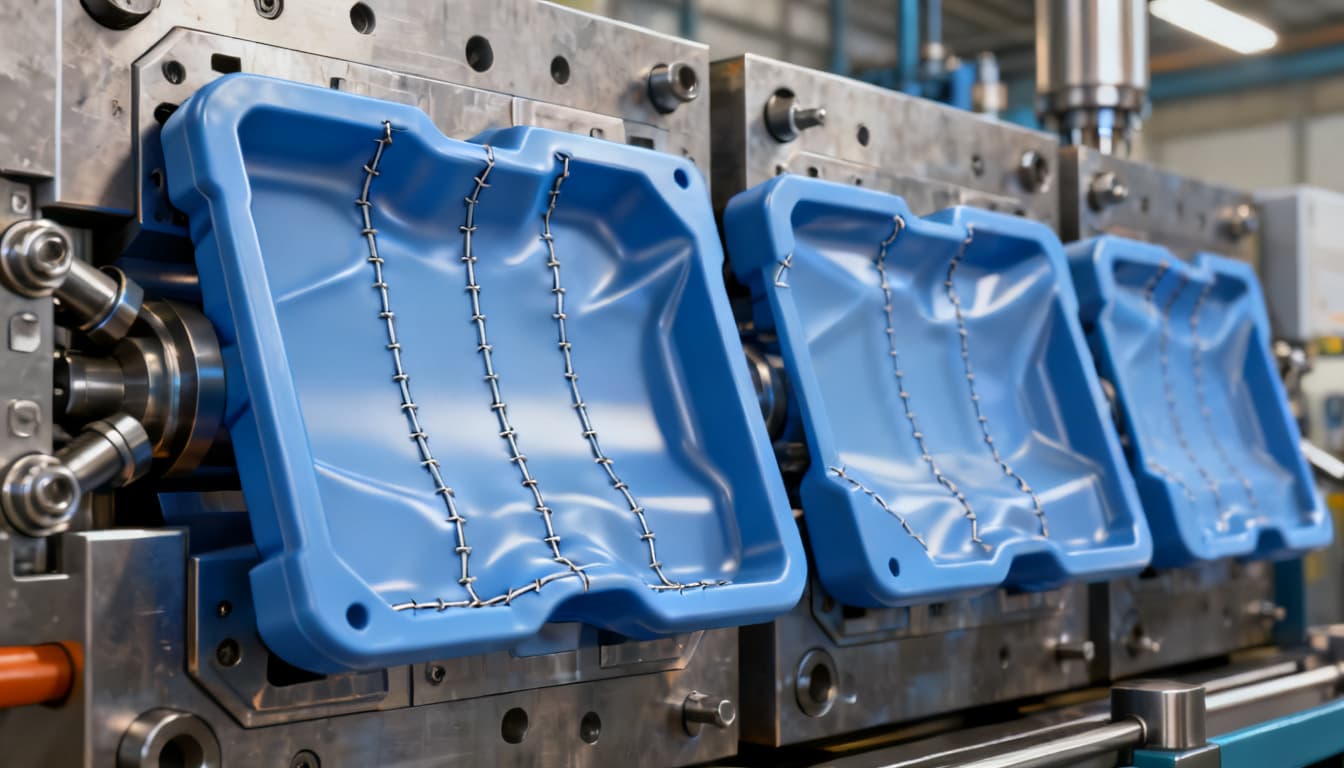
Weld Lines to Warpage: A Step-by-Step Troubleshooting Sequence for Injection Molding Defects
Last year, a medical device manufacturer scrapped 4,200 polycarbonate housings — roughly $87,000 in material and machine time — because a hairline weld line propagating from a boss feature cracked during drop testing. The initial response was textbook: bump barrel temperature by 10°C and increase in
Why Weld Lines and Warpage Demand a Systematic Troubleshooting Approach
Last year, a medical device manufacturer scrapped 4,200 polycarbonate housings — roughly $87,000 in material and machine time — because a hairline weld line propagating from a boss feature cracked during drop testing. The initial response was textbook: bump barrel temperature by 10°C and increase injection speed. The weld line didn't disappear. It simply migrated 3 mm closer to a snap-fit tab, where it failed again. Meanwhile, a consumer electronics supplier fought warpage on a battery tray for six weeks, cycling through cooling time adjustments that added 8 seconds per shot without improving flatness by a single millimeter.
These aren't isolated incidents. Elastron's defect guide documents how moisture-induced splay and differential cooling create cascading quality problems — where fixing one defect introduces another. The guide specifically notes that warpage stems from differential shrinkage rates across part geometry, not simply inadequate cooling time. HLC-metalparts reinforces this with a practical observation: relocating or adding an extra gate can shift a problematic weld line away from high-stress regions entirely — a mold-level solution that no amount of process tweaking can replicate.
The deeper problem, as Super-Ingenuity's engineering team documents, is that increasing cooling time adds cycle cost but rarely fixes warpage. The root cause typically lies in non-uniform wall thickness, unbalanced cooling circuits, or residual stress concentrated around gate locations. Ad-hoc fixes — cranking pack pressure, extending cooling, raising melt temperature — often mask symptoms while introducing flash, internal stress, or dimensional drift. What's needed is a structured, step-by-step sequence that traces each defect to its origin before applying a fix. This article provides exactly that: a methodical path from weld line detection through warpage correction, grounded in the physics of polymer flow and validated by production experience.
The Physics of Weld Lines and Warpage: Causes, Mechanisms, and Material Behavior
Weld lines form when two or more melt fronts converge inside the cavity and fail to fully knit together. RapidDirect defines them precisely: a line that emerges when flow fronts are unable to seamlessly merge or "weld" together, commonly found around holes, bosses, or any geometry that splits and rejoins the melt. At the molecular level, the polymer chains at each flow front have already begun cooling and orienting. When they meet, chain entanglement across the interface is limited — creating a mechanically weaker plane that behaves like a micro-notch.
Warpage operates through a different mechanism: differential shrinkage. As the part cools, thicker sections retain heat longer and shrink more than thinner sections. If the cooling rate varies across the part — due to unbalanced cooling circuits, non-uniform wall thickness, or asymmetric gate placement — internal stresses develop. When the part ejects, those stresses relax unevenly, pulling the geometry out of specification. Fictiv's troubleshooting resource notes that while weld lines are often considered cosmetic defects, they can also reduce impact resistance and tensile strength at the knit plane — making them a structural concern in load-bearing applications.
Understanding which category a defect falls into — machine-induced, mold-design-driven, or material-dependent — is the first diagnostic step. Dayamachinery's comprehensive 30-defect guide categorizes injection molding defects into three origins, and this framework applies directly to weld lines and warpage troubleshooting.
| Defect Origin Category | Weld Line Contributors | Warpage Contributors | Diagnostic Priority |
|---|---|---|---|
| Machine Settings | Low melt temperature, insufficient injection speed, low pack pressure | Excessive barrel temperature, inadequate cooling time, uneven clamp force | First — easiest to adjust, fastest to validate |
| Mold Design | Gate location causing multiple flow fronts, insufficient venting at knit point, cold slug traps | Non-uniform wall thickness, unbalanced cooling channels, poor gate placement creating asymmetric fill | Second — requires downtime but addresses root cause |
| Material Properties | High viscosity grade, inadequate drying, filler content affecting flow behavior | High shrinkage rate, semi-crystalline morphology, glass-fiber orientation anisotropy | Third — evaluate when machine and mold fixes fail |
This categorization matters because it prevents the common mistake of chasing machine adjustments when the mold itself needs modification. A weld line caused by a poorly placed gate won't disappear by raising melt temperature 15°C — it may become less visible, but the underlying knit weakness remains. Similarly, warpage driven by a 3 mm wall thickness variation won't resolve through extended cooling; the differential shrinkage is baked into the geometry.
Key Takeaway: Knit lines are inherent to the injection molding process whenever flow fronts split and rejoin. Complete elimination is rare. The engineering goal is to move them to non-critical areas and maximize knit strength through proper processing — a principle we'll operationalize in the troubleshooting sequence below.
Machine Adjustments vs. Mold Modifications: A Side-by-Side Fix Comparison
When a defect appears, the instinct is to reach for the machine controller — adjust a temperature setpoint, tweak injection velocity, or extend the hold timer. These changes take minutes and cost nothing in tooling. Mold modifications — relocating a gate, adding vents, rebalancing cooling circuits — require pulling the tool, machining, and re-qualifying. The downtime alone can cost $2,000–$8,000 per day depending on press size and production schedule. Yet mold-level fixes often deliver permanent solutions where process tweaks merely buy time.
Crescent Industries outlines eight distinct strategies for addressing weld lines, spanning design-for-manufacturability analysis, material selection, and processing parameters. Their guidance emphasizes that most weld lines don't weaken parts unless processed incorrectly — but when they do, the fix hierarchy should start with the least invasive option. First Mold's analysis reinforces this with a combined approach: product designers, mold technicians, and injection molding operators must collaborate, because weld lines sit at the intersection of part geometry, tool design, and process execution.
The table below maps specific fixes against defect types, with practical guidance on when each approach is appropriate.
| Defect | Machine Fix (Low Cost, Immediate) | Mold Fix (Higher Cost, Permanent) | Material Fix (Alternative Grade) | When to Escalate |
|---|---|---|---|---|
| Weld Line (Cosmetic) | Increase melt temperature 10–20°C; raise injection speed; boost mold temperature | Relocate gate to shift knit line to non-visible surface; add vent at knit point | Switch to lower-viscosity grade (higher MFR) | If line persists after 3 process iterations across 2 material lots |
| Weld Line (Structural) | Maximize pack pressure at knit zone; use profiled injection with high-speed initial fill | Add hot runner or second gate to eliminate flow-front collision; rapid mold heating above Tg | Reduce filler content; select grade with better knit-line strength retention | If tensile testing shows >30% strength loss at knit vs. bulk material |
| Warpage (Minor, <0.5 mm) | Reduce melt temperature; balance fill speed; adjust pack/hold pressure profile | Rebalance cooling circuits; adjust ejection timing | Switch to lower-shrinkage grade (e.g., amorphous vs. semi-crystalline) | If dimensional checks show variation across cavities in same tool |
| Warpage (Severe, >0.5 mm) | Extend cooling time (temporary); reduce mold temperature differential between halves | Redesign gate location for symmetric fill; add cooling channels; uniform wall thickness redesign | Add glass-fiber to reduce shrinkage (may introduce new warp from anisotropy) | If Cpk drops below 1.33 on critical dimensions |
Fictiv's troubleshooting guidance offers a practical machine-side starting point: increasing melt temperature and injection speed improves knit-line strength by giving flow fronts more thermal energy to entangle before freezing. But they also acknowledge that weld lines are difficult to eliminate completely — a reality that makes mold-level solutions like gate relocation the definitive fix when cosmetic or structural requirements are stringent.
Tip: Before committing to a mold modification, run a designed experiment (DOE) varying melt temperature, injection speed, and mold temperature across 3 levels each. If the defect responds to process changes but never fully resolves, the root cause is geometric — and mold work is justified. If the defect doesn't respond at all, check material drying and lot-to-lot viscosity variation first.
A Step-by-Step Troubleshooting Sequence: From Weld Line Detection to Warpage Correction
The following sequence is designed for the production floor — not the simulation lab. Each step builds on the previous one, and skipping ahead (jumping straight to mold modifications without verifying material condition, for example) wastes time and money. Work through these steps in order, documenting results at each stage.
Step 1: Identify Defect Type and Map Its Location. Not every surface line is a weld line, and not every dimensional deviation is warpage. Weld lines appear as hairline cracks or V-shaped notches precisely where two flow fronts meet — typically downstream of holes, bosses, or gate locations that split the melt. Warpage manifests as bowing, twisting, or dimensional drift from the nominal CAD geometry. Mark the defect location on the part drawing and note whether it appears in all cavities or only specific ones. Cavity-specific defects point to cooling imbalance or venting issues; all-cavity defects suggest material, machine setting, or gate design problems.
Step 2: Verify Material Condition and Melt Temperature. Elastron emphasizes that material used without proper predrying introduces moisture that causes splay and weakens knit lines. Check dryer dew point (should be ≤ -40°C for hygroscopic resins like nylon or PC) and residence time. Verify actual melt temperature with a needle pyrometer — don't trust the barrel setpoint alone. A melt that's 15°C below the material supplier's recommended mid-range can prevent flow fronts from knitting properly. For warpage, confirm that melt temperature isn't excessively high, which increases shrinkage during cooling.
Step 3: Evaluate Gate Location and Flow Pattern. HLC-metalparts' guidance is direct: relocating or adding a gate changes the flow pattern and can eliminate a problematic weld line or shift it to a non-critical area. Perform a short-shot study — incrementally fill the cavity from 60% to 98% full — and photograph each stage. The short-shot progression reveals exactly where flow fronts meet and whether the gate location produces balanced fill. For warpage, check whether the gate freezes before pack pressure fully transmits to thick sections; a gate that's too small or freezes prematurely prevents effective packing.
Step 4: Assess Cooling Uniformity and Wall Thickness. Super-Ingenuity's root cause analysis identifies non-uniform wall thickness and unbalanced cooling circuits as the primary drivers of warpage that cooling time adjustments cannot fix. Measure wall thickness at 5–8 points across the part using an ultrasonic gauge. A variation exceeding 10% of nominal wall thickness creates differential shrinkage that will warp the part regardless of process settings. Check cooling circuit flow rates with a flow meter; a 20% imbalance between circuits can produce measurable warpage.
Step 5: Apply Targeted Fixes Based on Root Cause. For weld lines where the knit is structurally critical, First Mold describes a rapid heating technique: before injection, briefly use high-temperature steam to raise the mold core temperature above the glass transition temperature (Tg) of the material, then switch to cold water for cooling and setting. This keeps the flow front molten longer, improving chain entanglement at the knit. For warpage, adjust the packing profile — a stepped profile with higher initial pressure that decays over time can compensate for differential shrinkage without introducing flash. Fictiv's advice on increasing melt temperature to improve knit line strength applies here, but with a critical caveat from Super-Ingenuity's flow marks guide: extreme packing pressure that achieves acceptable appearance can introduce internal stress that later manifests as warpage or environmental stress cracking. Balance is everything.
| Troubleshooting Step | Key Measurement / Tool | Target / Acceptance Criteria | Common Pitfall |
|---|---|---|---|
| 1. Defect Identification | Visual inspection, 10x loupe, part drawing markup | Confirm defect type; map to cavity number and location | Misidentifying flow marks or splay as weld lines |
| 2. Material Verification | Needle pyrometer, dew point meter, moisture analyzer | Melt temp within ±5°C of supplier mid-range; dew point ≤ -40°C | Trusting barrel setpoint without physical measurement |
| 3. Flow Pattern Analysis | Short-shot study (60–98% fill), high-speed camera | Balanced fill; knit line in non-critical zone | Skipping short-shots and guessing flow-front meeting point |
| 4. Cooling & Wall Thickness | Ultrasonic thickness gauge, flow meter, thermal camera | Wall thickness variation <10%; cooling circuit flow balanced within 5% | Measuring only one point and assuming uniformity |
| 5. Targeted Fix Application | DOE matrix, Cpk analysis, tensile test at knit line | Knit strength >70% of bulk; Cpk >1.33 on warpage-critical dimensions | Over-packing to fix appearance, creating residual stress |
Caution: When adjusting pack pressure to correct warpage, monitor for flash at the parting line and measure part weight consistency. A weight variation exceeding 0.3% across shots indicates unstable packing that can produce intermittent warpage. If you're fighting both weld lines and warpage simultaneously, prioritize the defect that affects function — a structural weld line failure is catastrophic, while minor warpage may be correctable through fixturing during cooling.
Troubleshooting FAQs: What Senior Engineers Ask About Weld Lines and Warpage
Q: Can weld lines be completely eliminated, or is relocation the only practical fix?
Complete elimination is rare because weld lines are inherent whenever flow fronts split around a core pin, boss, or other geometry and then rejoin. The most practical strategy, as HLC-metalparts documents, is relocating gates to shift the knit line to a low-stress, non-cosmetic area. If relocation isn't feasible — for example, in a part with multiple holes that can't be moved — focus on strengthening the knit through higher melt temperature, faster injection speed, and elevated mold temperature at the knit zone. In high-value tools, rapid mold heating above the material's Tg immediately before injection can dramatically improve knit strength without relocating gates.
Q: How do I differentiate a weld line from a flow mark or splay?
Weld lines appear as a distinct hairline crack or V-shaped notch precisely at the convergence point of two melt fronts — typically encircling a hole or radiating from a boss. Flow marks present as wavy, rippled surface patterns caused by uneven flow-front propagation speed, often appearing as concentric rings near the gate. Splay manifests as silvery or whitish streaks radiating from the gate area, caused by moisture, trapped gas, or thermal degradation. Elastron's defect guide notes that splay from undried material produces a characteristic pattern distinct from the linear discontinuity of a weld line. Location is diagnostic: if the defect traces the meeting path of two flow fronts, it's a weld line. If it fans out from the gate, it's likely splay or a flow mark.
Q: When is it cost-effective to modify the mold rather than tweak process parameters?
The tipping point arrives when the defect persists across multiple material lots and after a systematic DOE covering melt temperature, injection speed, mold temperature, and pack pressure. Crescent Industries advises conducting design-for-manufacturability analysis early — ideally during part design — to avoid costly retooling later. If the tool is already cut, calculate the cost of continued scrap, rework, or customer returns against the mold modification cost. A $6,000 gate relocation that eliminates a 3% scrap rate on a million-part annual volume pays back in under three months. Mold modifications like adding vents ($800–$1,500), rebalancing cooling circuits ($2,000–$4,000), or changing gate type ($3,000–$8,000) become cost-effective when process-only fixes require constant monitoring and still produce intermittent defects.
Q: What is the impact of glass-fiber reinforcement on weld line strength?
Glass-fiber reinforcement significantly reduces weld line strength because fibers orient parallel to the knit plane rather than bridging across it. In unreinforced resin, a well-processed weld line might retain 70–80% of bulk tensile strength. With 30% glass-fiber reinforcement, knit-line strength can drop to 40–50% of bulk — a critical consideration for structural parts. First Mold's rapid heating technique, which raises mold core temperature above Tg before injection, can improve fiber entanglement across the weld by keeping the melt mobile longer. Higher melt temperatures and faster fill speeds also help by reducing the cooling that occurs before flow fronts meet. Hot runner systems that eliminate cold runners reduce the temperature drop between plastication and cavity fill, further improving knit strength in fiber-reinforced grades.
Q: How can I validate that a warpage correction won't introduce new defects like sink marks or internal stress?
Run a mold flow simulation with the adjusted parameters before cutting steel — modern simulation packages accurately predict warpage, sink marks, and residual stress distribution. On the production floor, perform short-shot studies to verify the fill pattern hasn't shifted in a way that creates new gas traps or weld lines. Super-Ingenuity warns that extreme packing pressure applied to achieve acceptable appearance can introduce internal stress that later manifests as warpage or environmental stress cracking. Monitor part weight consistency across 50 consecutive shots; a standard deviation below 0.15% of mean part weight indicates stable packing. For critical applications, perform a solvent stress test or anneal parts to reveal residual stress before committing to full production. Iterative DOE on a single cavity before scaling to all cavities is the safest validation path.
Effective troubleshooting isn't about knowing every possible fix — it's about knowing which fix to apply first, and when to escalate. The sequence outlined here prioritizes the fastest, least expensive interventions before progressing to mold modifications. When you need support diagnosing a persistent weld line or warpage issue on a production tool, our engineering team can help with mold flow analysis, process optimization, and tooling recommendations tailored to your part geometry and material. Get a quote for troubleshooting support or new tooling consultation.
References & Further Reading
- 11 Injection Molding Defects and Troubleshooting — Elastron
- 28 Injection Molding Defects and How to Prevent Them — HLC Metal Parts
- Injection Molding Defects Troubleshooting Guide: Causes, Fixes, and Root Cause Paths — Super-Ingenuity
- Injection Molding 101: 30 Common Defects & Solutions Guide — Daya Machinery
- Weld Lines Analysis and Solutions — First Mold
- Injection Molding Weld Line: Its Causes, and How to Avoid It — RapidDirect
- Weld Lines | Injection Molding Troubleshooting — Fictiv
- 8 Ways to Fix Injection Molding Weld Lines — Crescent Industries
- Injection Molding Flow Marks: The Complete Troubleshooting & Prevention Guide — Super-Ingenuity
- Contact PandaMolding for Injection Molding Support